Chassis: Force India (EPM Technology) Class: F1 2014 Engine:Mercedes Benz PU106 1.6L Turbo V6 Fuel: Petrol Transmission:8 speed sequential (Mercedes) Brakes: Carbon/Carbon (AP Racing) 0 Weight: – Fuel Tank: ATL Year introduced: 2014

Pre Launch
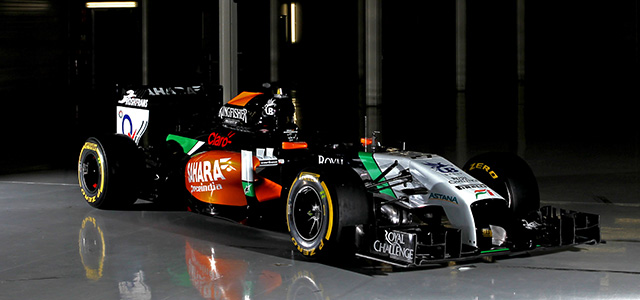
Force India was the first team to reveal an image of its full 2014 F1 car. What it showed was a surprisingly evolutionary design, with many features carrying over directly from the 2013 car.
“It doesn’t look hugely different, but it is; almost every single part is a new design, from the front wing right back to the diffuser” explains Andy Green, Force India Technical Director. “Its genetics still lie in the 2013 car, but we’ve had to achieve the same results in a slightly different way. From the nose backwards it looks quite similar. It’s a little bit ‘fatter’ for the increased cooling requirements, but we hope to trim that out during the early part of the season. To be competitive we have to develop and because there are so many areas that need significantly refining, optimising the performance of this car is going to be a big challenge.”
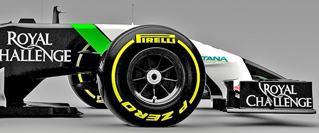
The image reveals little about the design of the nose, other than it is clearly much lower than that of the VJM06, but that is dictated by the regulations. However Green is open that the nose fitted to the car in the image and that it will use in Jerez is not the final specification version.
“Our nose is a launch spec and later we will have an updated front end of the car, which potentially is quite different. We had to take quite a pragmatic view of it and say we’ve got to go testing so we’ve got to get a car out of the door. As much as we want to push the boundaries of the impact structure, because we know how important they are for the whole car, we don’t have the resources to push it to the limit in our first iteration, so we need a banker. The nose that is on the launch car is a banker.”
This means that the VJM07 will be re-submitted for its crash tests at the Cranfield Impact Centre at some point between Jerez and the opening race of the year in Melbourne, Australia.
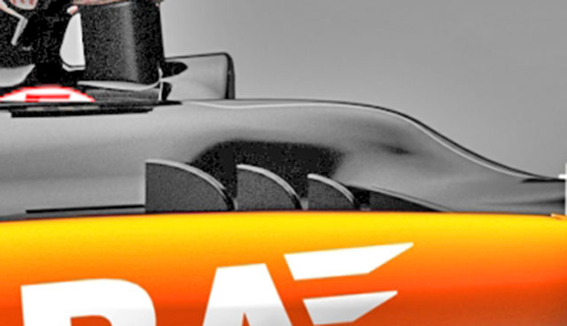
The car like all 2014 designs will require additional cooling, and the centre line gills evident on all recent Force India’s are again apparent, although seemingly a bit larger.
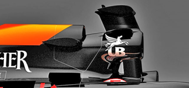
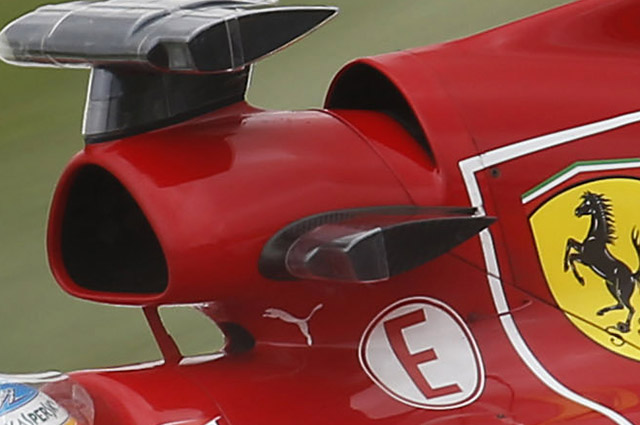
More interesting is the adoption of a Ferrari style cooling duct behind the roll hoop. These have in the past been used for the gearbox oil cooler but in 2014 solutions such as this will be common place as the turbo charger and MGU’s all require significant cooling. Compare the Force India version (above) with the 2013 Ferrari version (below)
TEST 01: JEREZ, SPAIN
The VJM07 had its formal reveal at the pre-season test in Jerez. The car was fully prepared for in track running rather than many cars which were shielded in some way or other.
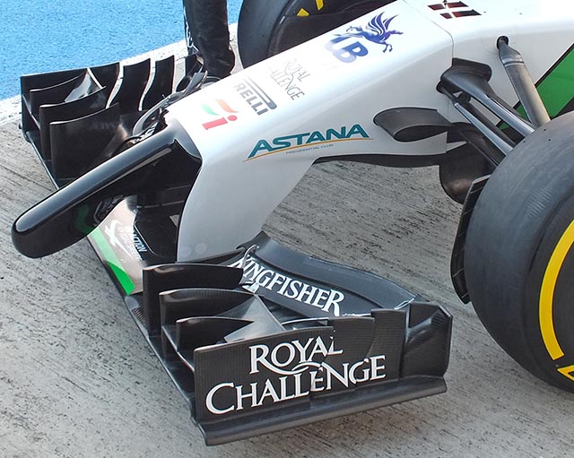
The nose of the VJM07 is similar in concept to others seen along the pit lane this season, with the unsightly low frontal crash structure very evident. Note the front wing detail.
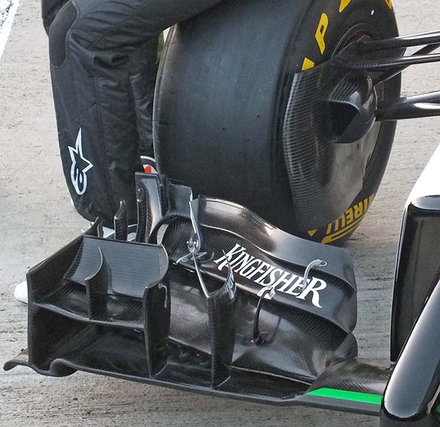
The intricate front wing of the VJM07 looks to be highly developed already. Note turning vane on the upper outer element. Note the brake duct design and the small blanking plate.
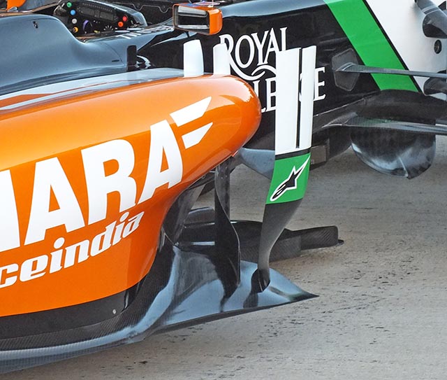
A look at the sidepod shape and the undercut, the turning vanes appear to largely be carry over components from 2013.
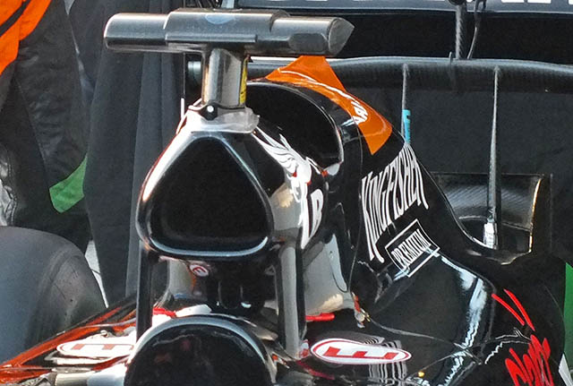
A better look at the roll hoop and additional cooling duct, it looks likely that this feeds the heat exchanger visible at the rear of the car (below)
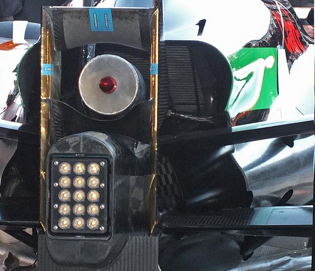
This is typically the location of the transmission oil cooler but the heat exchanger seems larger than normal, however the gearbox itself is larger than in previous years. Also evident in the above image is the exhaust exit (with end cap in place) the gas flows between two elements of the ‘monkey seat’ winglet. The central part of the underside of the upper element is coated with a thermal barrier, whilst the inner and trailing edges of the endplates are covered with Zircotec’s Thermohold Gold heat shield.
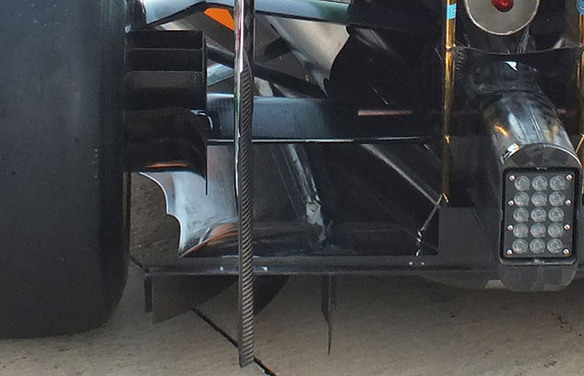
A look at the diffuser of the car reveals many intricate details, note the floor shape around the rear wheel and the shrouded driveshaft.
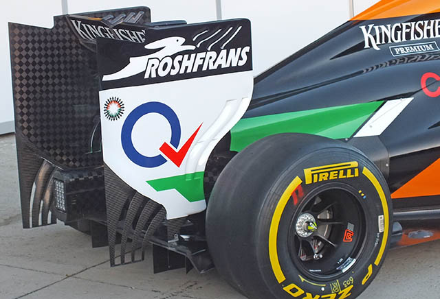
The rear wing endplate features the now standard serrated base and has twin slits toward the leading edge.
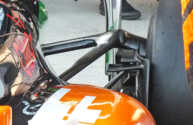
The upper wishbone outer pickup point on the rear suspension is highly distinctive, and worth further investigation.
TEST 01: SAKHIR, BAHRAIN
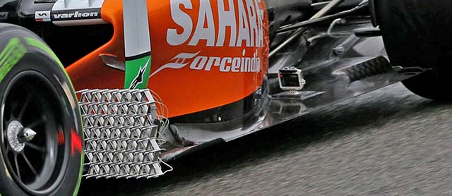
During the first test the Force India was fitted with a sensor array to monitor the air flow in the wake of the front wing, suspension and wheel. Note the GoPro style camera on the rear floor.
TEST 02: SAKHIR, BAHRAIN
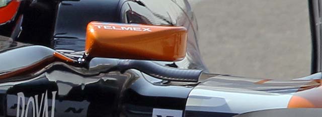
At the second test Force India replaced the turning vanes on top of the side pod with small flow conditioners.
TEST 03: SAKHIR, BAHRAIN
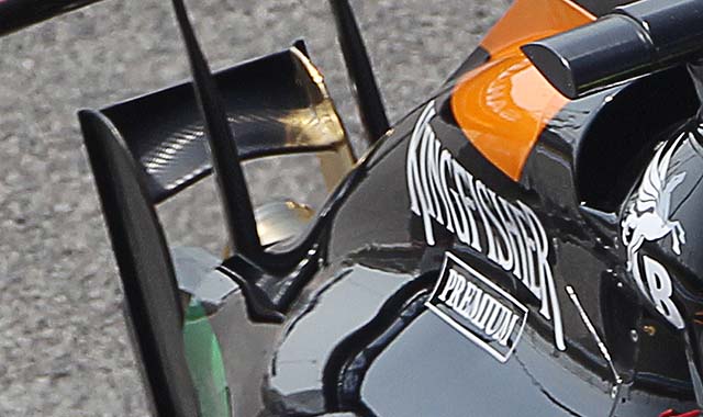
At the third test a new gold coating was applied to the rear end of the car, at first glance this may look like a reflection but there is without doubt some kind of over spray on the ‘money seat’ winglet.
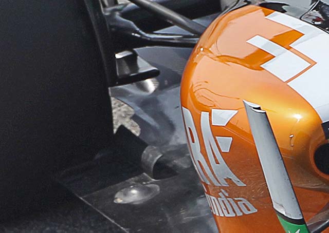
A nice look at the curved turning vane at the rear of the floor on the VJM07. Most cars on the grid have vanes in this area but few of them are curved like that.
RACE 01: ALBERT PARK, MELBOURNE, AUSTRALIA
Car 11
Chassis: VJM07-02
Result: 11th
Car 27
Chassis: VJM07-04
Result: 7th
Before the race Force India changed the low pressure fuel pump output configuration on both cars.
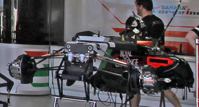
At Melbourne we get a first chance to look under the skin of the Force India, albeit in an incomplete state, the front bulkhead is very pain with a small opening for the master cylinders, the torsion bars are also clear to see.
RACE 02: SEPANG, MALAYSIA
Car 11
Chassis: VJM07-02
Result: DNS (Transmission Control)
Car 27
Chassis: VJM07-04
Result: 5th
Before the race Force India changed the following parts of the cars
11 Perez: Rear brake friction material, Gearbox hydraulic manifold, Parameters for gearbox hydraulic manifold change, Disable faulty backup brake pressure sensor.
27 Hulk: Water pump assembly
In Malaysia there was a chance to get a look under the bodywork of the VJM07 which could be one of the stronger cars of this season.
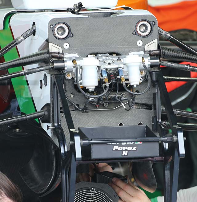
Looking at the front bulkhead of the VJM07, most of the expected details are evident, the torsion bars are clear to see near the top edge of the chassis, the cir clips holding them in place are just visible.
The white master cylinders are mounted to the front of the power steering rack (the silver part in the centre of the bulkhead). At the lower part of the bulkhead there are two small holes slightly offset to the drivers left, the purpose of these is not clear currently.
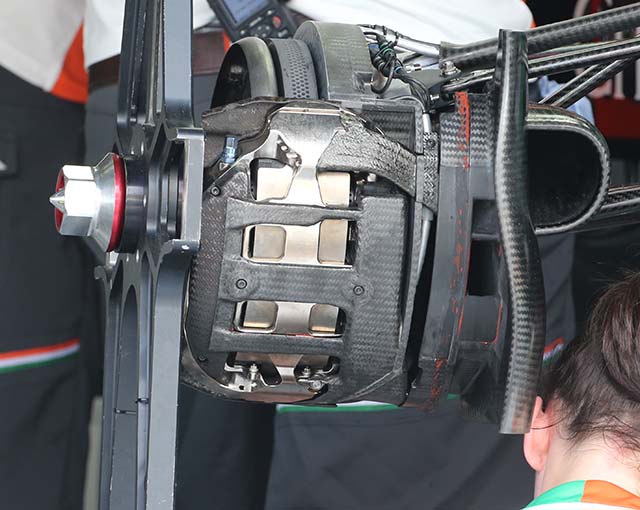
The front brake assembly is clear to see and conventional in design. The brake caliper is mounted at the leading edge of the disc.
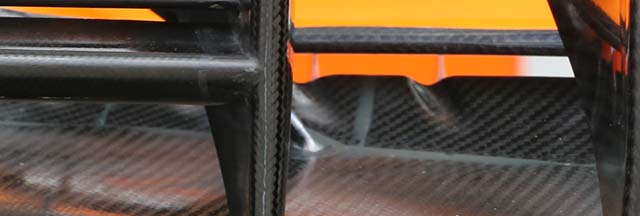
The front wing remains largely unchanged since the cars roll out at Jerez, but this image shows some of the smaller details not normally noticeable. Note the sculpting at the trailing edge of the upper unpainted element.
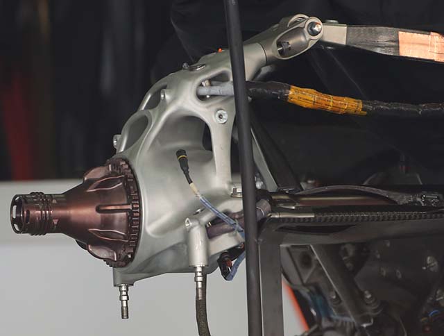
The rear upright on the VJM07 is really a work of art. Seen here with most components removed its flowing and highly optimised design is clear. A few years ago designing something like this would have been impossible let alone making it.
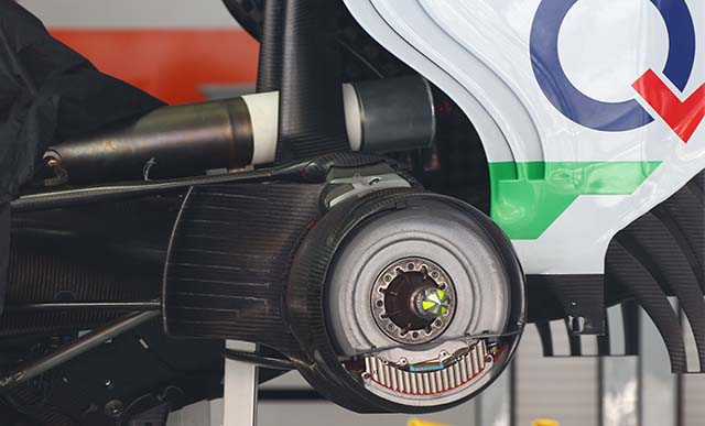
The upright is almost never seen in this form as it is usually covered in many aerodynamic and braking elements (above). Note the Zircotec ceramic thermal barrier coating on the tailpipe, this is to protect the rear wing supports from the heat.
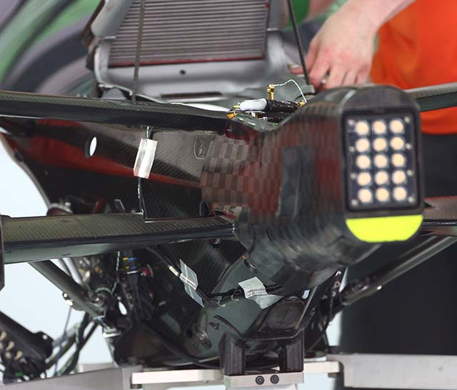
Force India buys its gearbox from McLaren, here the eight speed carbon fibre design can be seen from the rear with the rear crash structure closest to the camera. The oil cooler is visible at the top of the image.
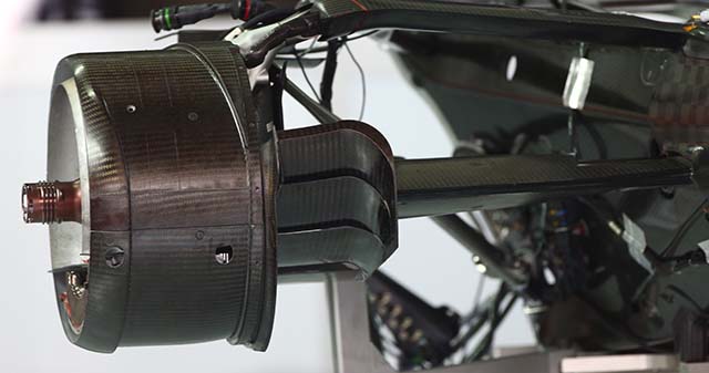
Outboard of the transmission the rear brake drum and ‘cooling duct’ cascade of winglets.
RACE 03: SAKHIR, BAHRAIN
Car 11
Chassis: VJM07-02
Result: 3rd
Car 27
Chassis: VJM07-04
Result: 5th
Before the race Force India changed the following parts of the cars
Car 27: RHS rear brake temperature sensor, ERS coolant header tank fixing, Gearbox bypass valve
Car 11: LHS front brake barrel seal
Force India had a good day in Bahrain, taking full advantage of its Mercedes power units. But in the pits we got a good look at the installation of the power unit and it highlighted one of the key challenges of the 2014 rulebook.
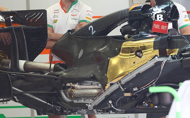
The sheer amount of heat shielding is clear the car has a second skin of bodywork with air having passed through the radiator ducts not directly passing over any other internal components. The notable exception to this is the exhaust header which peeks through a window in the heat shield.
On the roll hoop there are two inlets, one feeds the internal combustion engine whilst the other duct feeds the gearbox oil cooler as can clearly be seen above.
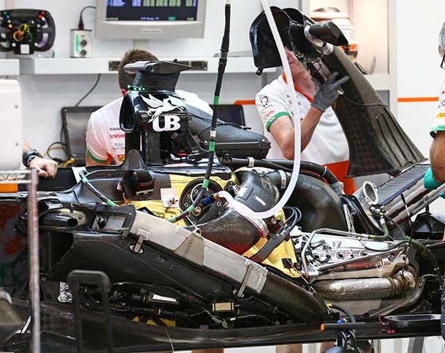
With the ducting and heat shedding removed however the installation of the power unit is clearer (above). The side pod duct is clear to see to the left of the image with the side impact structure also evident. Behind the roll hoop the air filter housing can be seen. To the lower right of the image the Mercedes ‘Pegasus’ V6 can be seen as can the gearbox oil cooler.
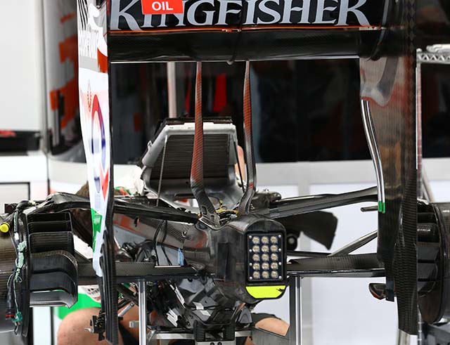
A nice look at the rear wing support and how it mounts to both the transmission casing and the wing itself.
