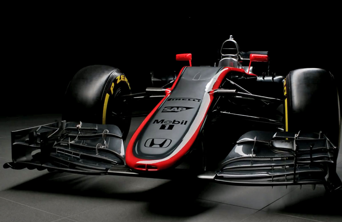
The McLaren MP4-30 is a clear evolution of last years MP4-29. With a stable rule set the majority of the basic lessons from 2014 have clearly carried over but with the major difference being the installation of the Honda RA615H power unit.
“Our restructured and strengthened engineering departments have gained the conviction to embark on a number of changes of direction. With that in mind, the MP4-30 has been developed to provide us with the most effective and practical base package. It is a foundation – offering up a number of new exploratory development paths for our engineers, aerodynamicists and drivers to pursue during the season, and on into next year.
The car has been aerodynamically developed over the winter, and the result is a pretty, elegant design with a refined nose-box solution, slimmed rear-end packaging – particularly around the gearbox – and the incorporation of an all-new power unit under its tightly contoured bodywork” the official press release reads.
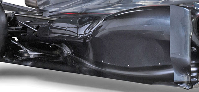
That tightly contoured bodywork is immediately apparent looking at the side of the car, which features a substantial undercut ate the rear of the sidepod. The leading edge of the side pod is also just about visible above and also features a notable undercut. The whole side pod appear to be much smaller than that used on the MP4-29 (below)
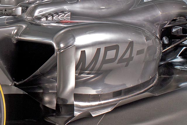
The tighter packaging of the sidepod is an indication that the cooling arrangement of the Honda power unit may well be notably different to that of the Mercedes used in the MP4-29. However in 2014 McLaren like all teams learned a lot of lessons about cooling the new power units and most have found ways to improve in this area.
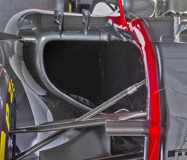
The side pod duct on the MP4-30 seems smaller than that of that of the MP4-29 (below) again this is likely due to lessons learned about the cooling demands of the new power units. An indication that this is the case comes from the slightly exposed side impact structure, which doubles as the upper stay for the side pod mounted turning vane. These side impact structures are a common part to all cars.
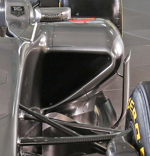
A key part of the cooling for the car comes via the roll hoop duct (below) which also feeds combustion air to the compressor, thought to be mounted at the front of the Honda V6 in an arrangement very similar to that of the Mercedes.

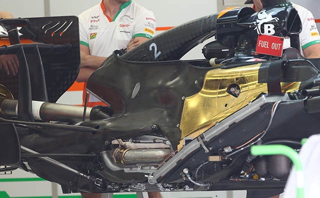
The lower section of the duct feeds the combustion air to the compressor, while the upper section feeds a heat exchanger mounted above the bell housing. This layout is very similar to that used by the Mercedes runners in 2014, see the Force India layout below for comparison.
It is also generally similar in concept to that seen on the MP4-29 (below), though where that had four of its roll hoop supports exposed the MP4-30 only has two visible.

There has been much interest in the nose of the MP4-30, which complies with the new rules relating to the front impact structure. Interestingly its tip (complete with driver cooling duct) sits a fair way forward of the wing support itself.
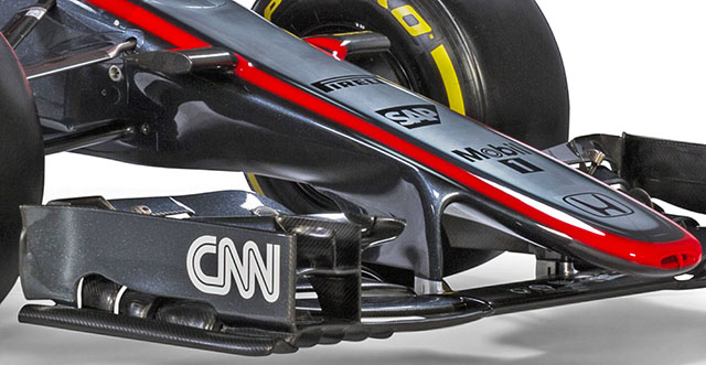
There is significant sculpting on the underside of the nose as McLaren’s aerodynamics department attempt to regain some of the losses caused by having a wider nose. Note the mandatory camera mounting points.
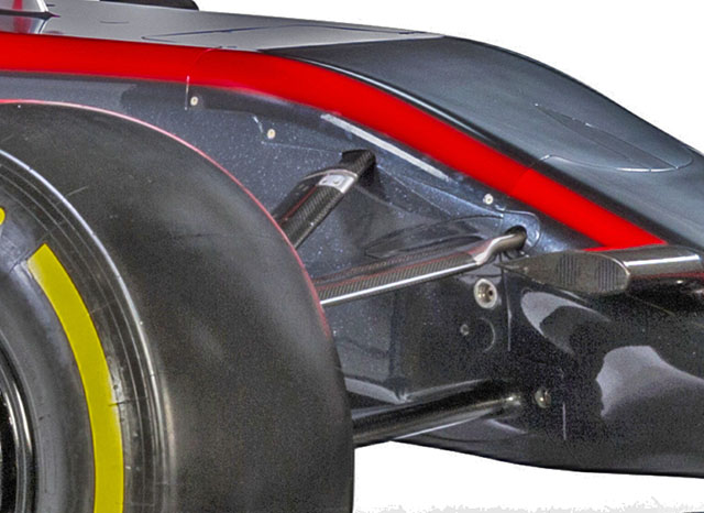
The front of the monocoque is an area of interest on the car. Looking at the panel lines it appears that a removable vanity panel has been added on the top of the front of the chassis. It serves a largely aerodynamic purpose, shielding the inboard pushrod mounting point and the front suspension components which appear, at least to some extent, to be mounted on top of the chassis. The front bulkhead appears to have a fairly complex shape compared to recent designs, with the inboard wishbone pickups seeming to sit on forward projections though that has yet to be fully revealed.
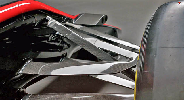
The pushrod actuated front suspension has some very nice sculpting on the wishbones, something shown very nicely in the MP4-30 launch video.
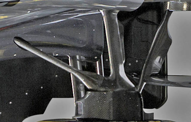
It is a similar story at the rear of the car, especially looking at the trailing element of the upper rear wishbone, it was this area last year where McLaren fitted the controversial ‘mushrooms’, it remains to be seen if these will re-appear.
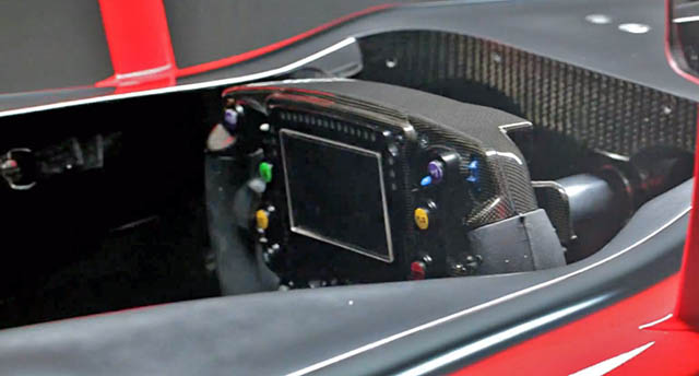
A look at the steering wheel of the MP4-30. More details of this will likely emerge at the first test.
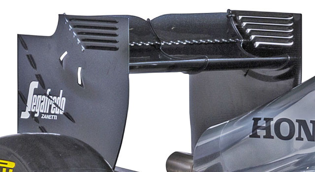
The rear wing on the launch specification MP4-30 features a number of concepts carried over from the MP4-29 including the serrated edges in the slot gap. Note also the small vanes on the endplate and additional vents.
TESTING
At Jerez and at the following tests in Barcelona the McLaren had a troubled test, the engineers from both Honda and McLaren spent most of the tim in Spain tracking down elusive technical problems in the power unit. As a result there was not much opportunity to get a good look over the cars. During the little running completed by the MP4-30 it was clear that the Honda RA615H Power unit is significantly different to the other three designs used in F1, specifically due to its raspy pulse jet style exhaust note. The reasons for this are not yet clear.
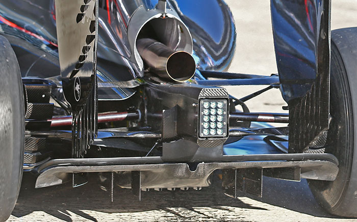
Here we get a good look at the diffuser used on the MP4-30 in Jerez, note the lines of vortex generators on the rear wing end plate. Additionally of interest are the flow conditioners mounted either side of the rear crash structure.
RACES: Australia, Malaysia, China & Bahrain
The opening races of the 2015 season went rather like testing for the McLaren-Honda team, with a lot of unreliability and poor on track performance. However McLaren continued to develop the car despite its issues. Its drivers claiming that the MP4-30 lacks downforce.
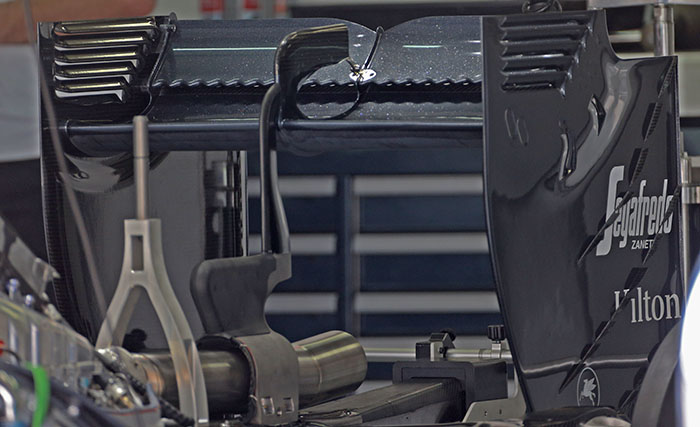
A look at the rear wing of the car, note the serrations on the lower edge of the upper flap. The central support of the wing carries the DRS actuation and with the engine cover removed its complex shape is revealed, with a cantilever like portion sitting above the y-lon wing support. The Y section of the support is much tighter to the tail pipe than it ever was in 2014.
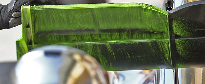
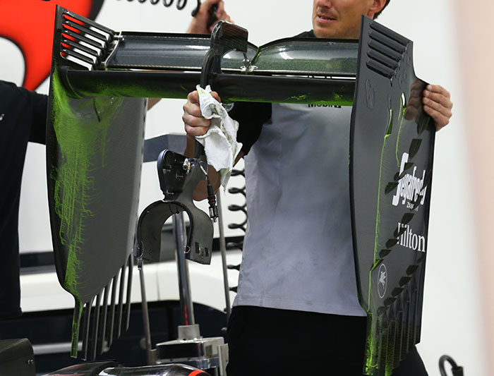
A look at the crucial rear and underside of the wing following a flow vis run in Bahrain. A similar test was conducted on the diffuser and outer face of the rear wing end plate with some fascinating results.
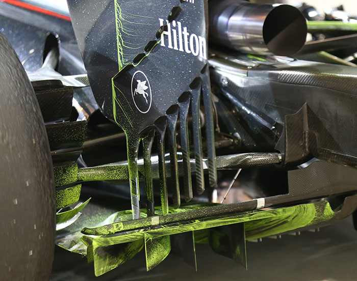
With the whole wing assembly in the process of being removed interesting flow vis results can be seen as can the mounting pylon (below).
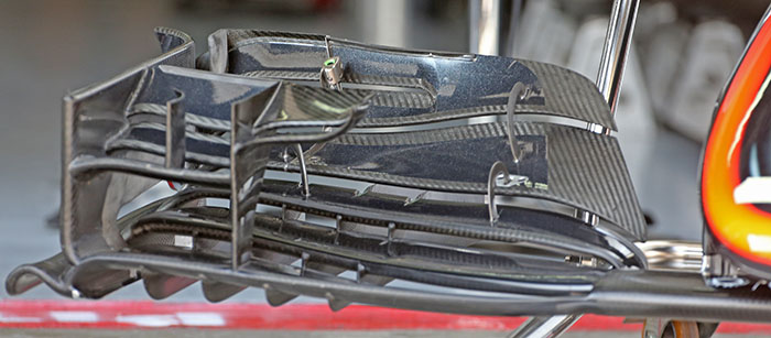
The front wing of the MP4-30 is relatively conventional with many complex elements (below).
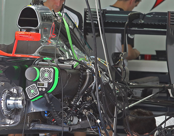
Here we get a good look under the skin of the MP4-30, note the centrally mounted ‘spine’ cooler.
The upper and lower side impact structures are clearly visible as is the rear wing support – ‘Y’ with exhaust removed.
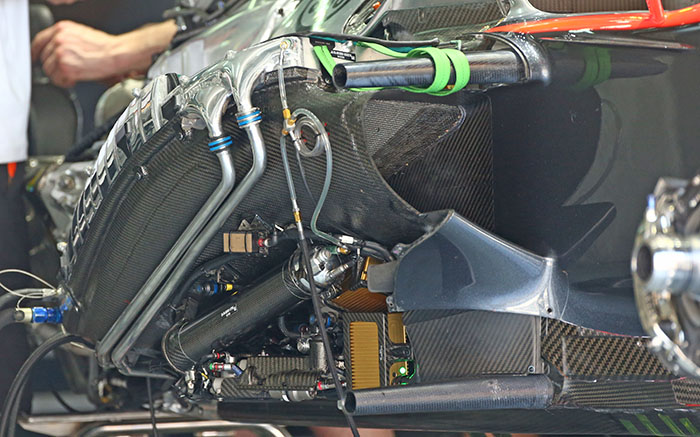
The layout on the right hand side is quite distinct with a totally different cooling layout. The intercooler appears to be in this stack of coolers.
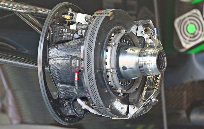
The front brake setup on the MP4-30 with the shrouding and cooling ducts removed. McLaren is the only car in Formula 1 to use the Japanese Akebono callipers.
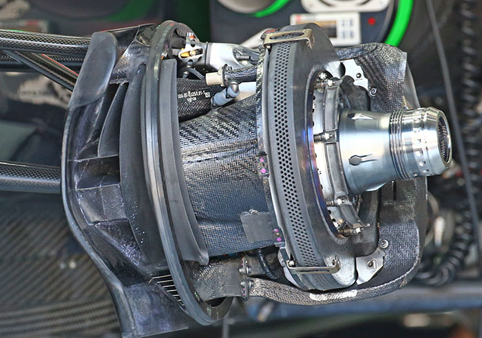
With the cooling ducts added the look of the front brakes transforms with the complex arrangement of cooling channels visible on the inner face.
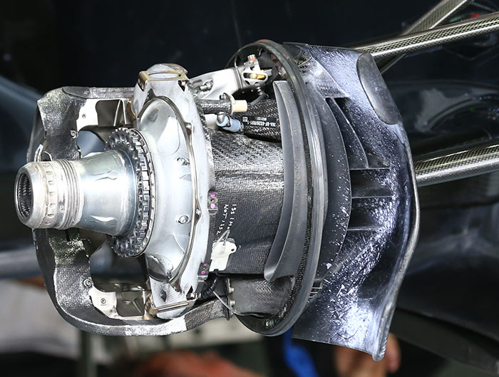
With some of the ducting added but the discs removed another good look can be had of the front brake set up. Here its can be seen that the lower segment of the ducting feeds cooling air to the caliper while the upper ducts feed air to the disc face. The inner face of the brake cooling plate is spattered with flow vis dye.
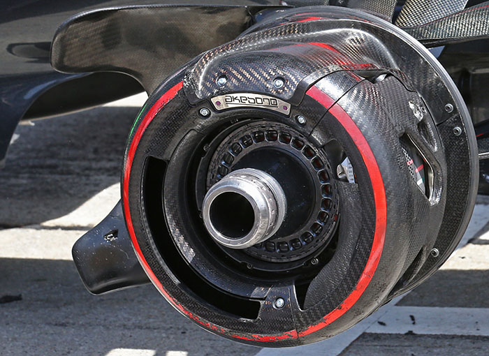
The fully assembled brakes feature a number of small openings around the disc, these are for cooling. Airflow around the brakes is crucial in the 2015 season, it is an area of significant development, largely conducted using CFD. Fully assembled and fitted to the car the brake and hub assembly features the so called ‘blown nut’ which is used to tune the airflow around the front wheels.
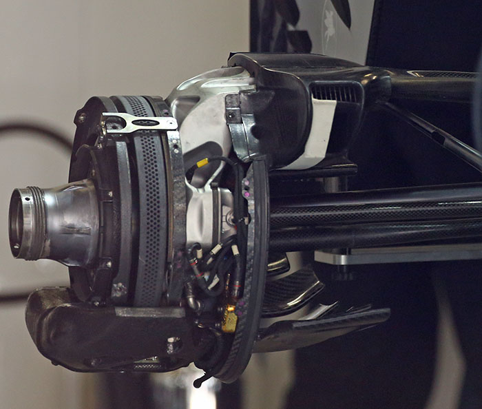
The rear brake setup features the calliper mounted at the lowest possible position on the disc to lower the centre of gravity.
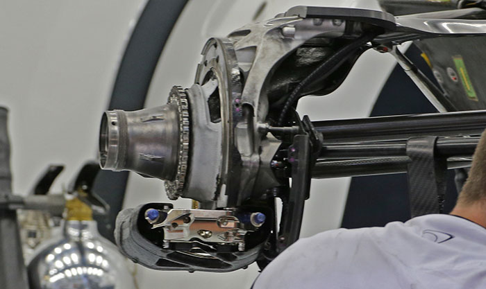
With the cooling shrouds and ducts removed the design of the rear upright can be seen.
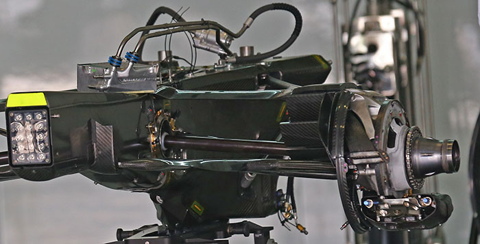
A look at the transmission, rear suspension and brakes of the McLaren MP4-30. The gearbox features a carbon fibre casing. Note the brake discs are removed in this image.
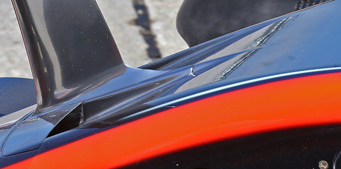
In Malaysia McLaren introduced a nose duct, rather than being for cooling these ducts are to do with the flow around, and under the nose. The exit ducts are fed by channels running in front of the bulkhead of the car (below). The torsion bars can just be seen nestled behind the steering rack.
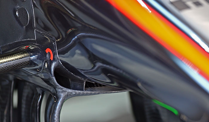
The air is fed to these ducts via a Red Bull style scoop under the nose (below)
With the ducting removed the shape and layout of the front bulkhead is clear(ish) to see. The opening at the front of the chassis is very similar to the layout used on the front of the 2014 car.
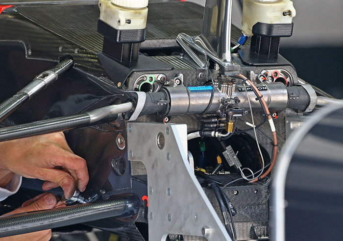
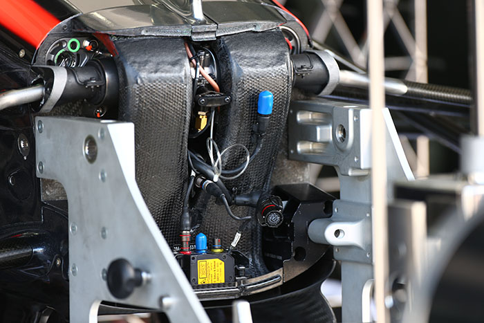
Notably absent from the front bulkhead are the master cylinders, the new nose heigh regulations in 2015 have seriously reduced the available volume at front of the car. So it appears that the master cylinders are mounted inside the front bulkhead. The angle of the front of the chassis can be seen and is slightly more gradual than that seen on the vanity panel.
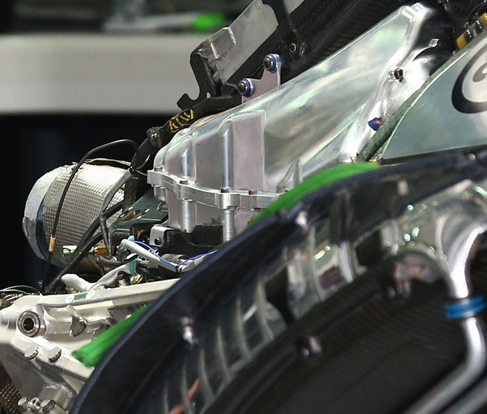
A look at the Honda RA615H V6 engine reveals that it appears to have a machined aluminium plenum whereas every other engine used in F1 has a composite component. The reasons for this are not clear. Another good look can be had at the central ‘spine cooler.’
The RA615H has until now been a little enigmatic but we can now reveal more of its design. Immediatey apparent is the use of a Birmann type exhaust layout, something used on the 2014 Mercedes, which can give much better gas flow to the turbine and allowing for better energy recovery from the MGU-H. Mercedes switched to the more common Sulzer type exhaust manifold in 2015.
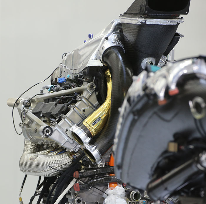
In this image the ducting to the intercooler, mounted in the right hand side pod of the MP4-30 can be seen. The pipe coated in a gold coloured heat shield appears to supply the air from the compressor to the intercooler, while the sister pipe (carbon fibre black) seems to feed the combustion air back to the plenum.
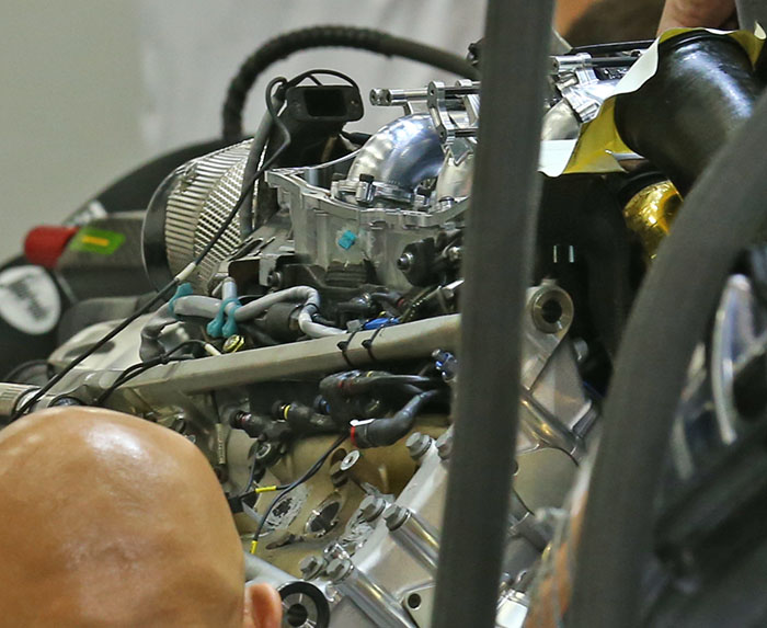
A look at the top of the engine with the plenum removed, as well as apparently the injectors and covers.
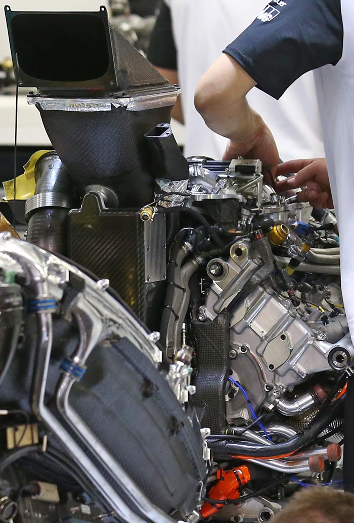
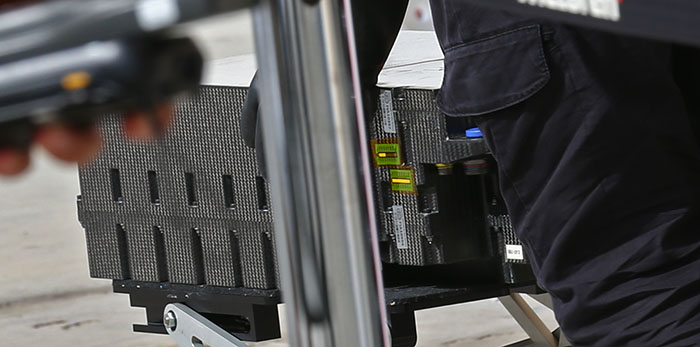
A glimpse of the battery pack on the McLaren. FIA Seals, temperature strips and high power connectors are all evident. This unit is mounted at the base of the chassis behind the driver and under the fuel cell (below).
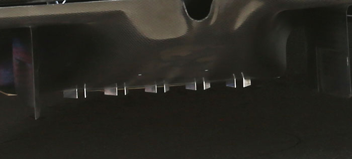
Under the centre of the diffuser the McLaren features a number of tiny turning vanes. McLaren has been using flow vis dye to try to visualise the air flow over this region of the car (below).
In some races with hotter ambient temperatures the McLaren is fitted with these additional centre line coolers. Common on the current generation of F1 cars.

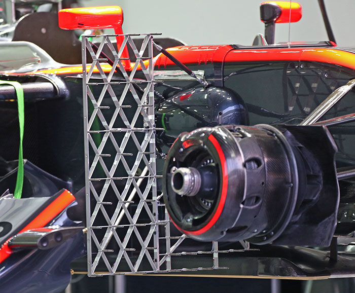
Aerodynamic evaluation runs continue with McLaren using sensor arrays on the car such as this one with a range of air speed/pressure sensors. Other smaller examples are also used.
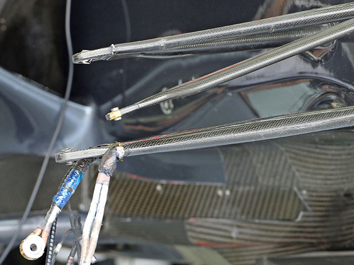
A look at the front suspension with the upright and brake removed, the rod ends are encased in carbon fibre, and the wheel tethers can be seen.
