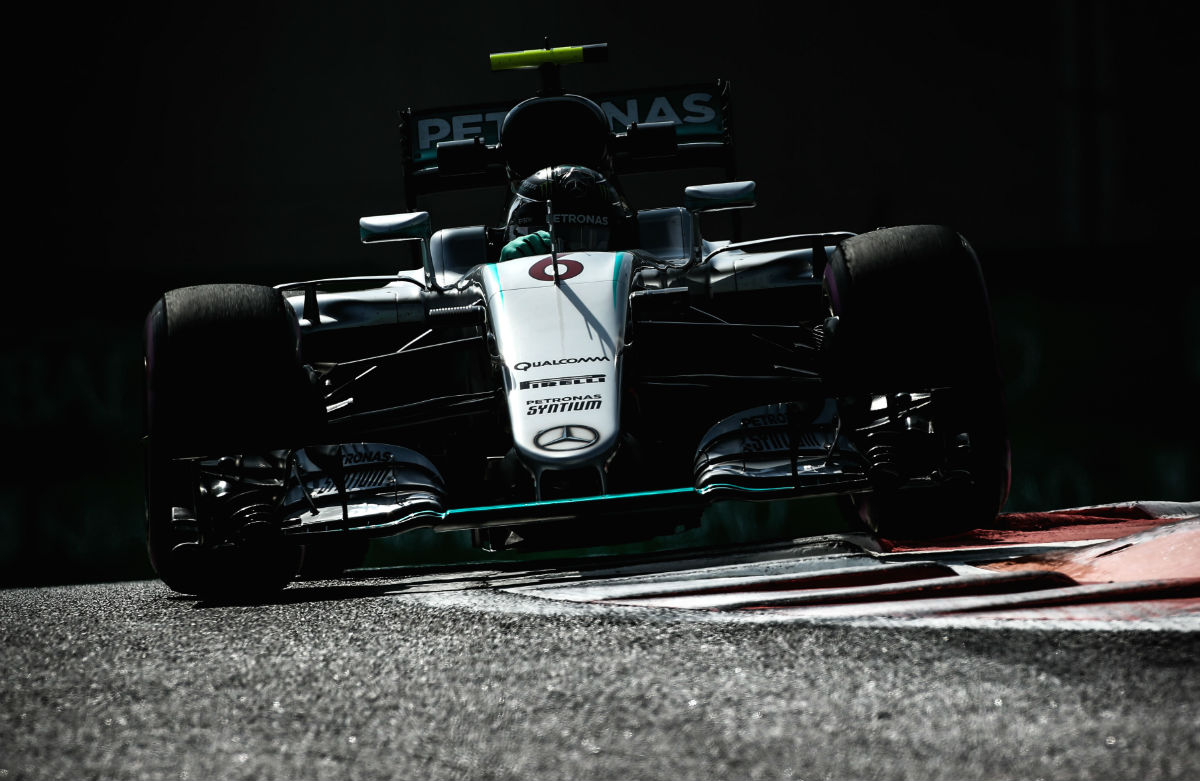
The Mercedes W07 ran for the first time during a private 100km test on the Silverstone International circuit in the early months of 2016. Despite winning the last two world titles Mercedes showed no sign of slowing its development rate as it pushed for a third crown.
As with many 2016 cars the W07 is a superficially conventional design with many design cues coming directly from the W06 and W05, but Paddy Lowe claims that under the skin the W07 wakes the W05 (one of the neatest modern racing cars every built) look agricultural.
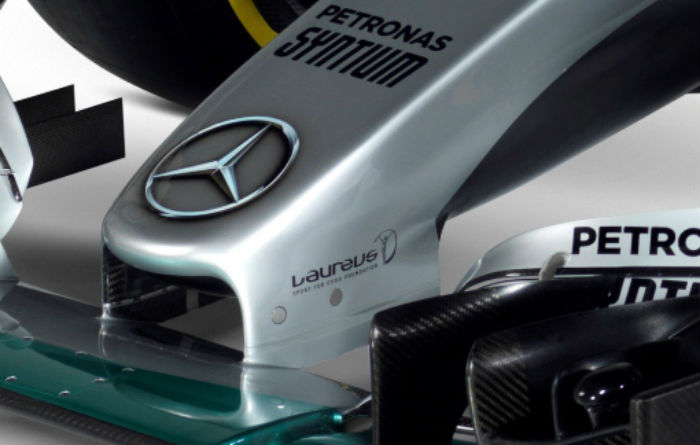
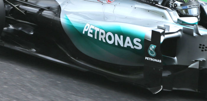
At the front of the car the nose is largely a carry over of concept from the W06 (below) with the front wing again protruding almost entirely ahead of the front impact structure, and mounted by a pair of joints which are tiny considering the load passing through them.
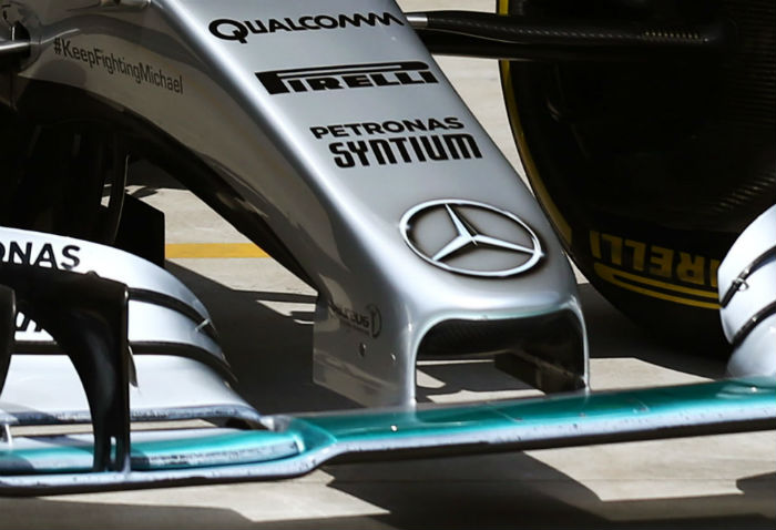
The front suspension is a conventional pushrod layout (at least externally) though not obvious in the images released so far it almost certainly retains the blended lower wishbone seen on the W05 and W06.
However Lowe teased a little about the internal suspension layout in the teams official launch press kit. “But we aim to make minor revolutions wherever we can – even within a small context. We may look at a completely new packaging solution or suspension concept, for instance.” Frustratingly it is not clear if he is saying that they have done this or he is just using it as an example.
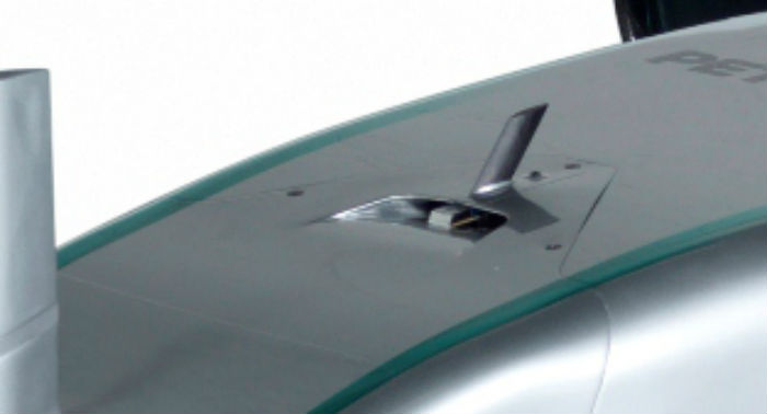
There is a small duct on the top of the chassis just ahead of one of the cars communication antenna, it is likely that this is for driver cooling. The W06 had a similar fixture.
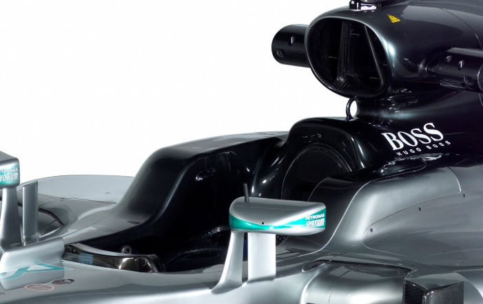
The area around the cockpit is one of much interest on the W07, it has the larger headrests mandated in the 2016 technical regulations. The sides are now 20mm higher and have to pass a side impact test of 50kN (up from just 15kN in 2015). But most of the real interest is focussed on the airbox and roll hoop of the W07.
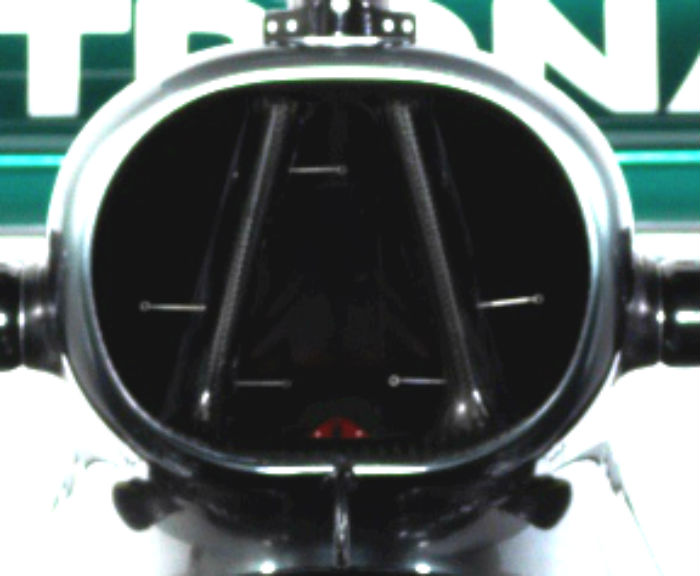
From the images seen so far what at first glance appear to be multiple sections within the airbox are in fact air flow sensors located in the duct suggesting that this car was likely shot during the Silverstone test and is still instrumented.
The roll structure itself appears to be the main triangular members forming the A shape in the middle of the duct, though they may simply be bracing for the main outer section which itself could be structural. The roll hoop also has an unusual curved support rather like the handle on an old cider jug. This at first glance looks like it is the wrong shape but Mercedes has better FEA than a casual set of eyes.
Overall The air duct itself is extremely large, perhaps similar in size to that of the Toro Rosso STR10 in 2015 (below).
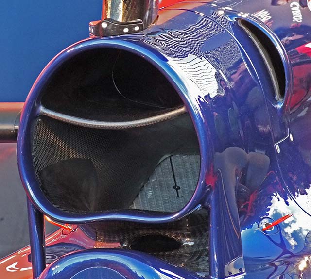
Relocating some of the cooling from the sidepods to the roll hoop is an approach exploited by Toro Rosso in recent seasons but is a trend started by Toyota with the unraced TF110 which relocated the ducting for the gearbox oil coolers from the sidepods to the region near the airbox. By doing this teams like Toro Rosso have been able to produce designs with much smaller sidepods.
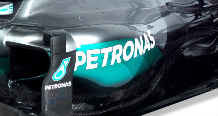
It seems that this has been the aim of Mercedes with the W07 (above), compare its sidepodes with that of the W06 (below)
The centre of that A feeds the power unit with combustion air, the two other segments either side of it are for cooling various sub components under the engine cover though at present it is not clear which (we cannot wait to see this region with the bodywork removed though this may not happen until Melbourne) they are a larger and different alternative to the chassis ears used on some cars in recent years.
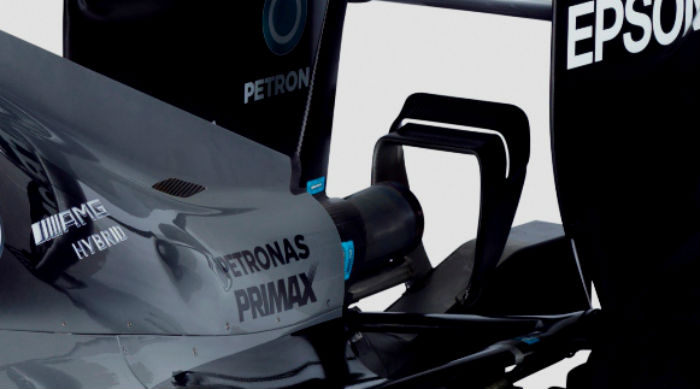
At the rear of the car the Mercedes features twin wastegate exits sat either side of the tailpipe, it revealed this design feature on social media long before the car was fully revealed. The rear wing support appears to be a tight ‘Y-lon’ shape over both the tailpipe and the wastegates.
In terms of the power unit Mercedes has yet to reveal much detail other than that there has been extensive development.
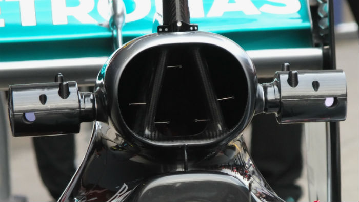
A much clearer look at the airbox on the W07. The team is reluctant to reveal what the outer segments cool but it will become apparent in Melbourne.
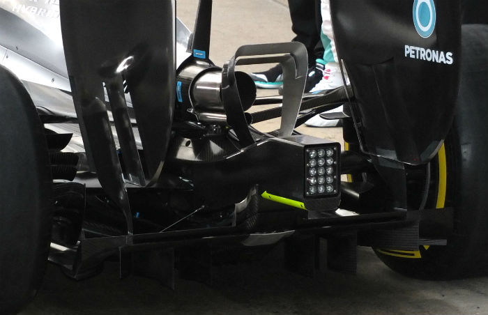
A look at the rear of the W07, note the twin wastegate pipes, and the winglet sitting downstream of the exhaust exit.
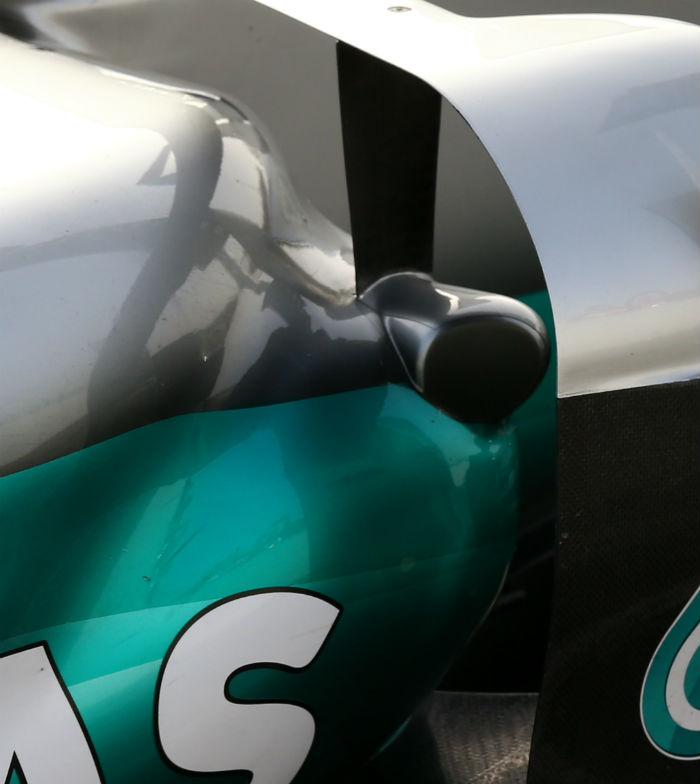
The leading edge of the sidepod on the W07 is extremely sculpted, with the bodywork hugging components like the side impact structure very tightly indeed

A serrated windscreen features on the W07 as it did on both the W06 and W05.
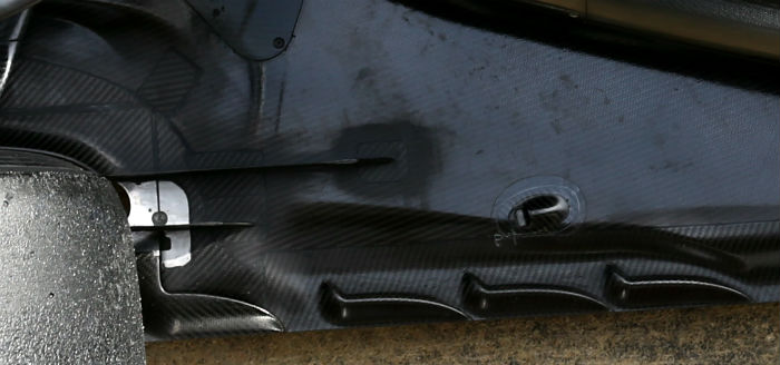
A look at the aerodynamic detailing around the rear floor of the W07, this is still a crucial area of development for all teams. It is possible they are still trying to minimise the impact of the rear wheel on the diffuser.
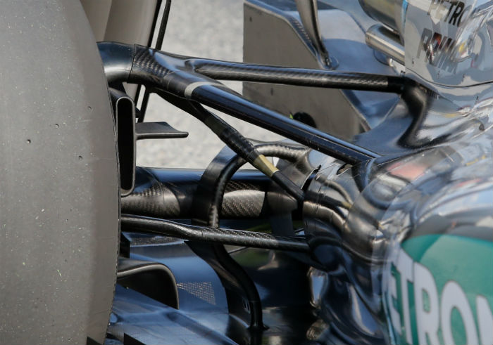
Downstream of that detail is the rear suspension, the pull rod layout is clear to see, note the blended rear wishbone and driveshaft.
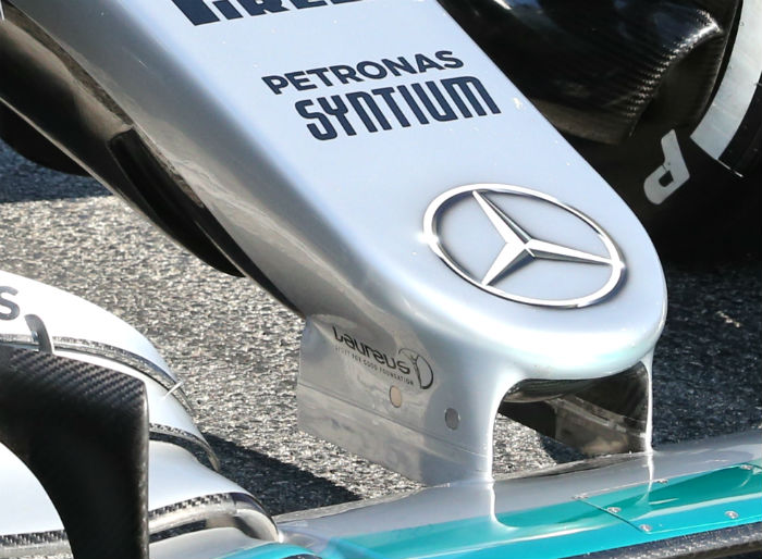
Late on in the first test Mercedes fitted a new ducted nose. Similar in concept to the one used on the Toro Rosso the new nose has an air inlet on its underside toward the leading edge. The nose itself is narrower and the front wing supports are closer together and taper outward slightly. While RCE can confirm that the new nose was subjected to the FIA deflection tests in Barcelona we cannot say for sure that it failed those tests as reported elsewhere.
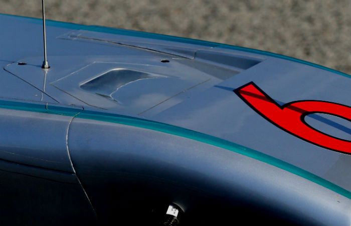
The air ducted from under the nose exits on the upper bodywork near the front of the chassis.
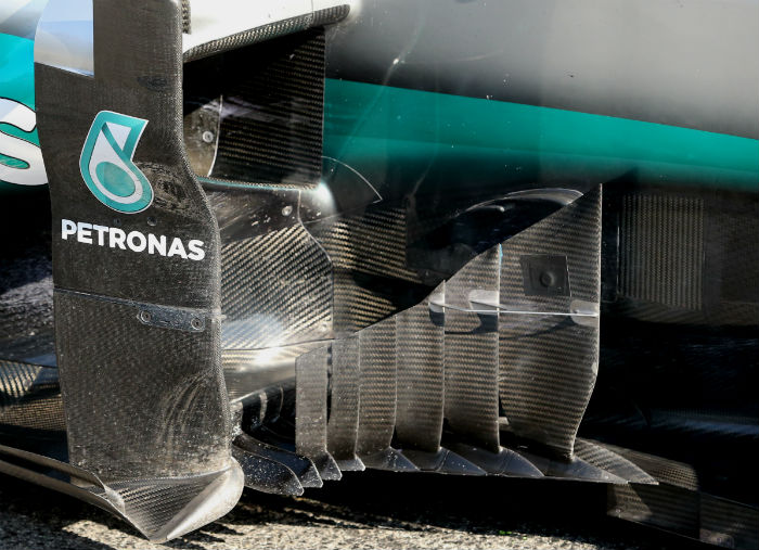
Another update introduced during the first test was a very intricate new design of barge board, its multiple elements taking the concept used by Lotus to an extreme level. Note the bracing between the leading elements.
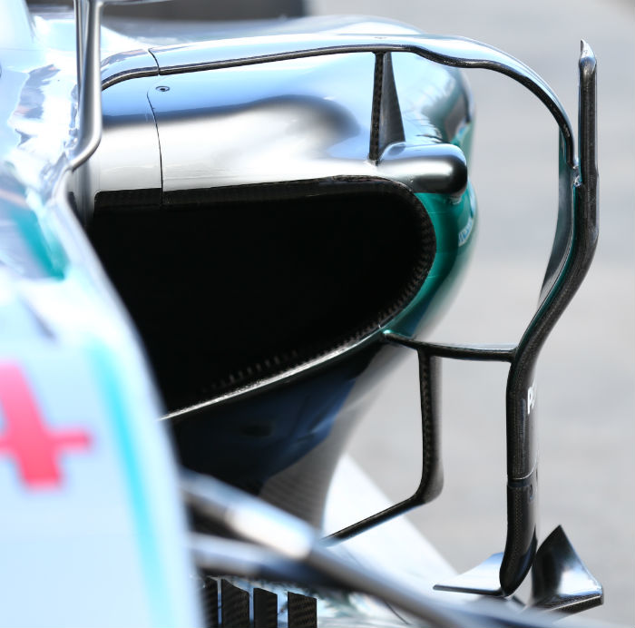
At Melbourne the W07 arrived with a notable aerodynamic upgrade featuring a number of new highly intricate parts. Most noticeable was the complex ‘pod wing’ array of turning vanes/flow conditioners, probably the most complex seen to date.
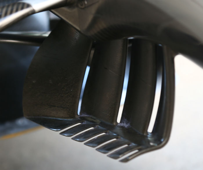
The undernose ‘ears’ have been reworked extensively and now have a multi element designing with a horizontal lower section.
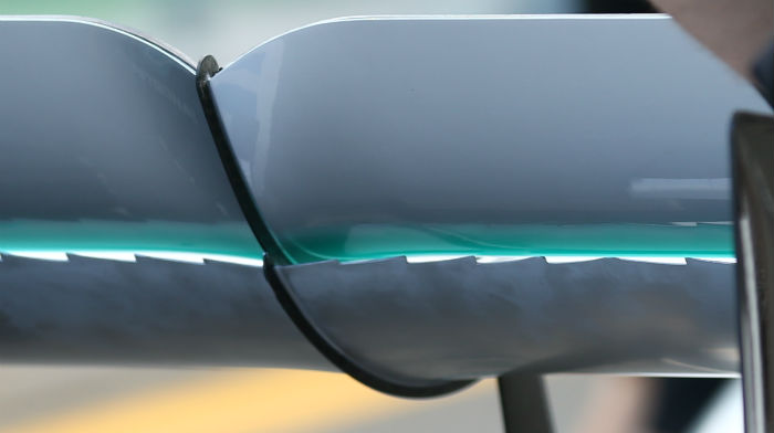
A new rear wing was fitted to the car with a fascinating jagged trailing edge to the lower element. It will be very interesting to hear how it functions and its purpose (which may be to do with flow separation, or rather minimising it)
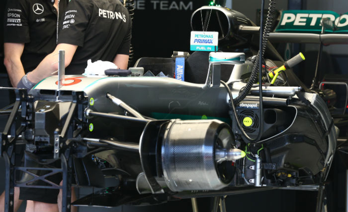
The Mercedes W07 has a similar level of underbody neatness to the W05, a car Paddy Lowe describes as the neatest car he has ever worked on. Most of the mechanical components under the bodywork are packaged behind covers.
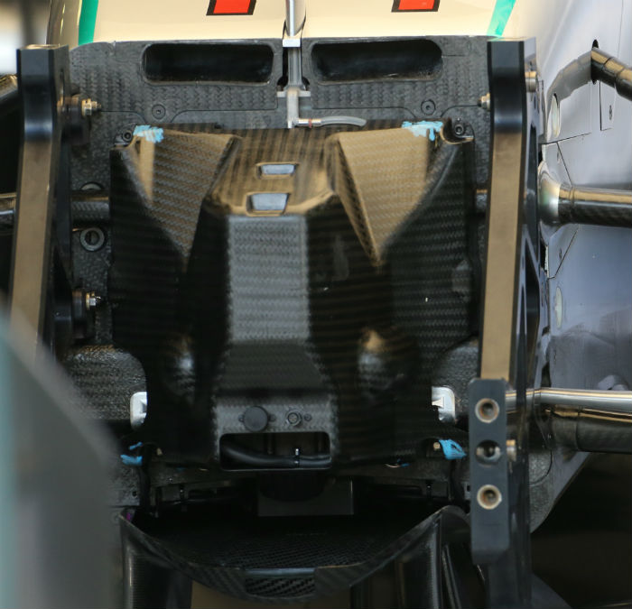
This is notable on the front bulkhead, where most cars have torsion bars, master cylinders and electrical components on display with the nose removed, often behind a protective carbon fibre basket, the Mercedes has a simple panel covering it all up. Looks a bit like a 1970’s sci fi prop to our eyes!
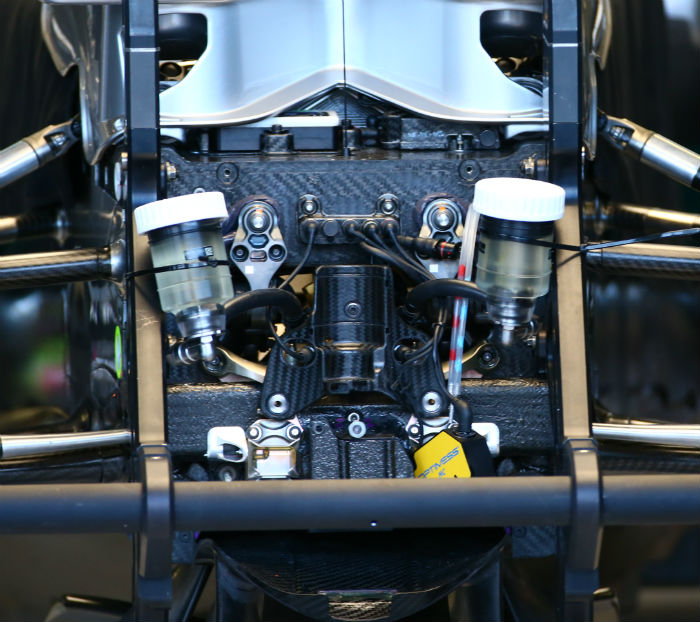
Here with the bulkhead cover removed the master cylinders are clear to see, though out of position in this shot. Note the electrical components mounted on top of the chassis and under the vanity panel.
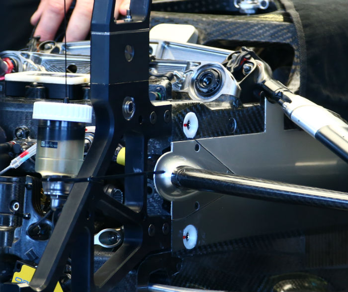
With the vanity panel removed the rectangular shape of the front of the W07’s tub is clear to see. Note the front suspension components mounted on top of the tub. It is not clear from this image but it may be that the W07 has an unconventional inboard suspension layout.
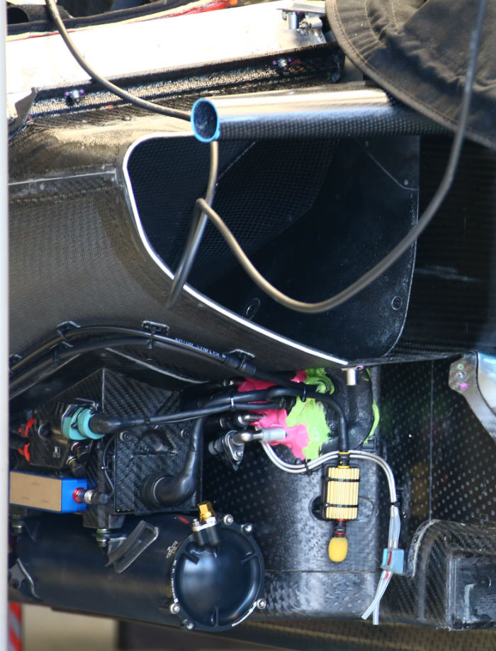
A glimpse of the right hand sidepod with the component cover removed below the main duct, the layout is still incredibly neat. Note the upper side impact structure.
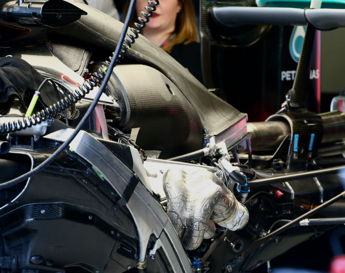
With the engine cover and some heatshields removed this image shows the general layout of the rear of the W07. The power unit is visually very similar to that used by Mercedes from the 2015 Italian Grand Prix onwards and there is expected to be a substantial upgrade in this area after the first four or five races. The purpose of the side ducts on the roll hoop is now clear, they feed a heat exchanger mounted above the bell housing, an arrangement not all that different to the layout seen on the McLaren. Note the ‘Y-lon’ style rear wing support mounting on the composite casing of the transmission.
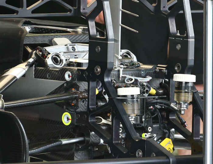
Another view of the front end of the Mercedes with its stepped front bulkhead with some of the suspension parts mounted on top of the chassis.
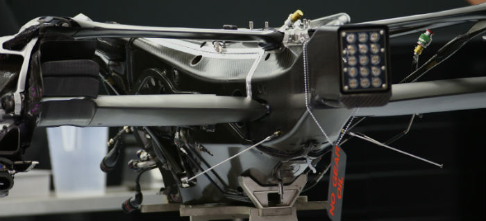
A look at the composite casing of the Mercedes transmission, it also features a metallic inner section.
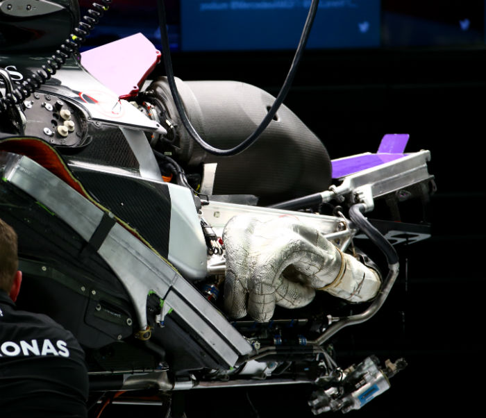
The Mercedes power unit mounted at the rear of the chassis and transmission removed.
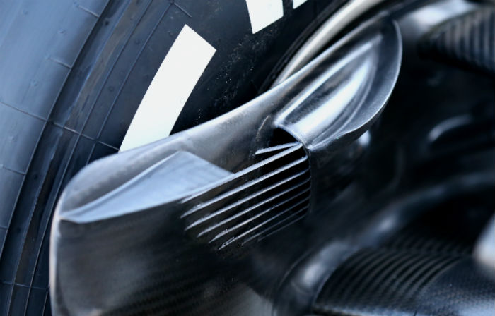
The level of complexity of the Mercedes is still the highest in Formula 1. This is illustrated by this series of tiny elements on the front brake duct if the car. Its likely that they serve a dual role, firstly to prevent debris entering the sensitive brake cooling system and secondly an aerodynamic flow conditioning role. It may be that this concept offers a drag reduction over the more commonly used wire mesh.
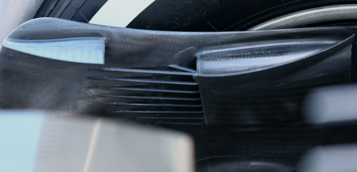
A look at the leading edge of the floor on the Mercedes, note the tiny strand of material linking two elements, it is likely that this serves a legality purpose on floor shape and width. The front stay is also extremely thin. A similar part can be seen at the rear of this section of floor.
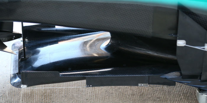
A look inside the nosecone of the Mercedes reveals the inner channels running from the vent on its underside up to the exit duct on the top of the chassis.
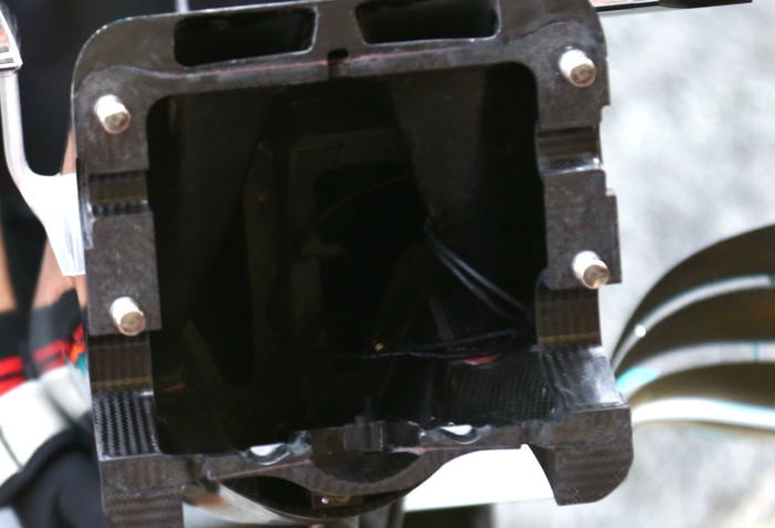
The internal front suspension of the W07 note the central element between the two pushrods as well as the torsion bar mounts.
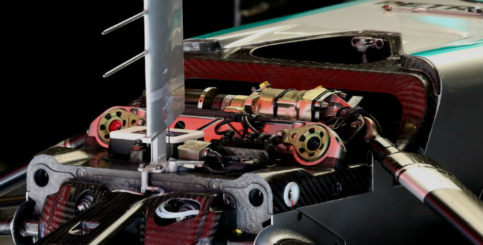
All of these parts are essentially mounted on top of the chassis rather than inside it.
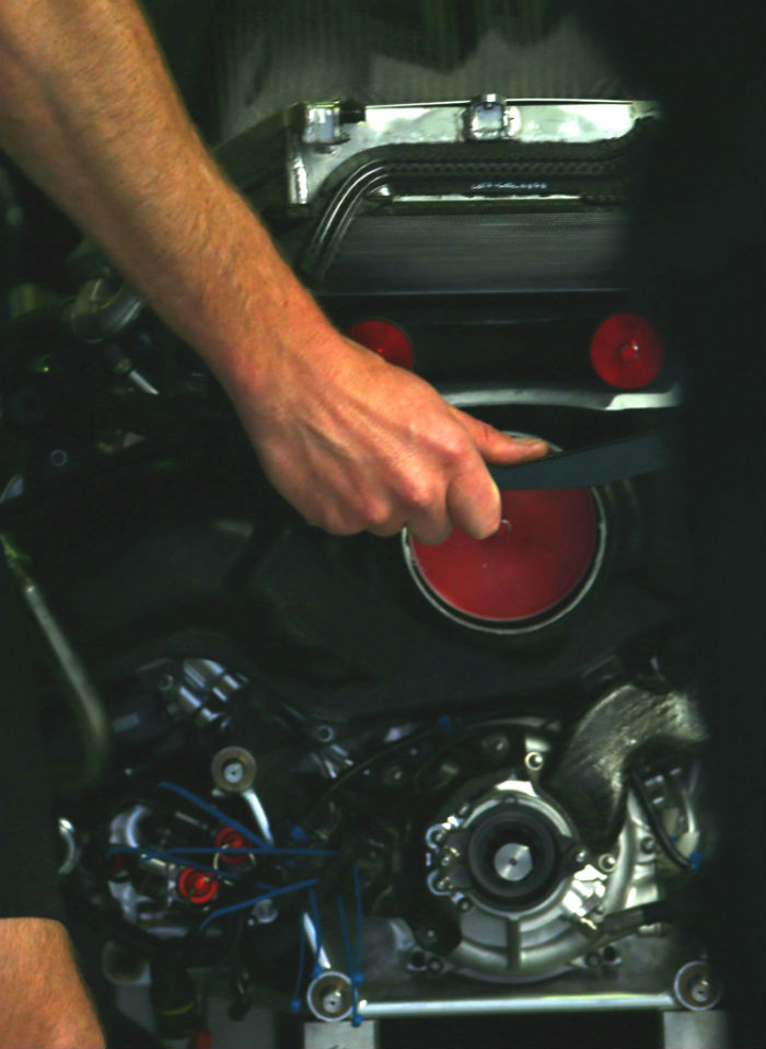
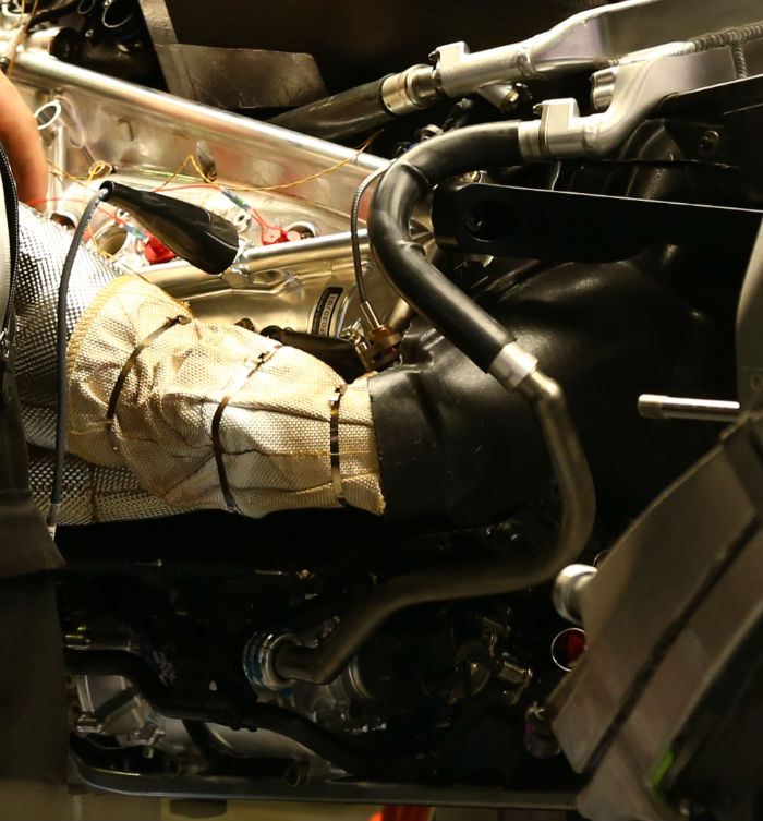
A rare look at the rear face of the Mercedes power unit, the shrouded turbine entry pipes can be seen as can the tail pipe (with a large bung intstalled) as well as the wastegate exits (with smaller red bungs)
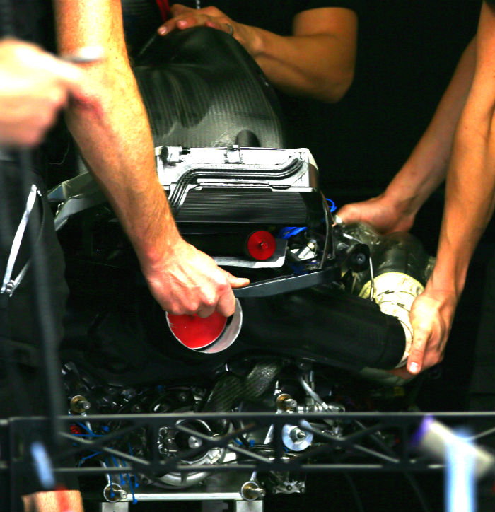
Looking more closely at the exhaust collector an exhaust wrap is cable tied around it acting as a thermal barrier, with a composite shroud around the turbine entry and the turbine itself, it is likely that this has a ceramic coating on the inside to allow such a material to be used in such a high temperature environment.
Spanish Grand Prix crash
An incorrectly set engine mode switch on Nico Rosberg’s steering wheel at the start of the Spanish Grand Prix lead to the dramatic retirement of both Mercedes W07s on the opening lap of the race.
The shunt between Nico Rosberg and Lewis Hamilton in Barcelona highlights not only the complexity of the current cars from a drivers perspective but also the variance in steering wheel layout between the two Mercedes drivers.
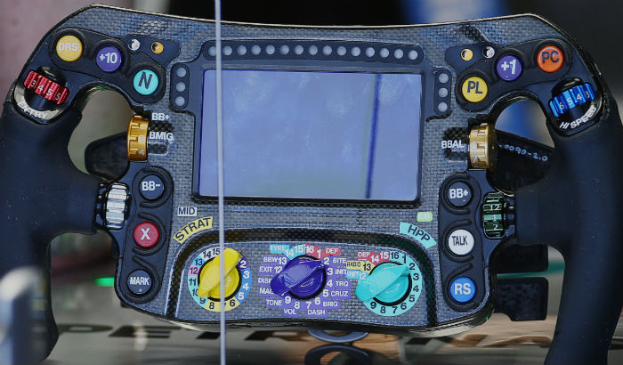
Comparing Hamilton’s wheel (above) with Rosberg’s (below) the differences are clear to see, barely any of the buttons are located in the same positions and most of the rotary switches differ too. The main strategy rotary is the same for both, while Hamilton has his power unit mode selected on the right hand rotary marked ‘HPP’ the functionality on Rosberg’s version is different.
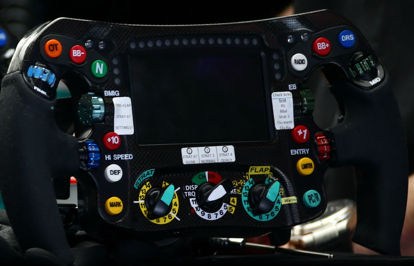
At Barcelona the two Mercedes drivers set their cars into a ‘launch mode’ a power unit mapping setting that ensures the best getaway and ERS deployment off the line. As usual coming out of turn 3 both drivers went to select ‘race mode’ but for some reason Rosberg failed to select his mode properly and ended up losing power as the ERS appeared to go into a recovery mode at the wrong point. To regain power Rosberg hit the overtake button (top left – orange button marked OT) and moved to cover Hamilton, but by this point he had a 16kph deficit to the Englishman and the two collided. It seems likely that Rosberg had one of his rotary switches in the wrong position and Hamilton did not, if that is the case then it seems unlikely that Rosberg could have held off the Englishman has the pair not collided.
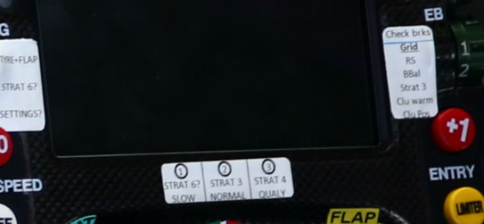
Something worth noting looking at the two steering wheels is that Rosberg’s wheel features three instruction stickers to remind the driver of which settings must be completed at various points in the pre-race procedure. It could be that this suggests that Rosberg is less confident in the positioning and function of the various switches on his wheel and needs more guidance on what mode is required when, and perhaps excited by making a good overtaking maneuver on his rival in turn 1 seemingly forgot to change his mapping to race mode (Strat 3) and either did nothing or selected a different mode altogether.
Ultimately the cause of the collision was Rosberg failing to select the correct mode on the opening lap, and this lead directly to Hamilton attempting to pass for the lead on the exit of turn 3.
The FIA Stewards took the following opinion.
The incident concerned started when Car 6 dropped into an incorrect power
mode, as set by the driver prior to the start. This created a significant power
differential between Car 6 and Car 44 at the exit of Turn 3 coming onto the
straight, resulting in as much as a 17kph speed difference between the two cars
on the straight. Car 6 moved to the right to defend his position, as is his right
under Art 27.7 of the Sporting regulations. Simultaneously Car 44 as the
significantly faster car with, at that time, apparent space on the inside, moved to
make the pass. Art 27.7 requires the leading driver to leave room, if there is a
“significant portion” of the car attempting to pass alongside. Car 44 had a
portion of his front wing inside Car 6 small fractions of a second prior to Car 44
having to leave the right side of the track to avoid an initial collision, which may
have led him to believe he had the right to space on the right. Once on the grass
on the side of the track Car 44 was no longer in control of the situation.
Having heard extensively from both drivers and from the team, the Stewards
determined that Car 6 had the right to make the maneuver that he did and that
Car 44’s attempt to overtake was reasonable, and that the convergence of
events led neither driver to be wholly or predominantly at fault, and therefore take
no further action.
At Monaco it was possible to get an extremely good look at the Mercedes power unit. So far this season the engineers at Brixworth have used up 21 upgrade tokens (of the 32 allowed per season).
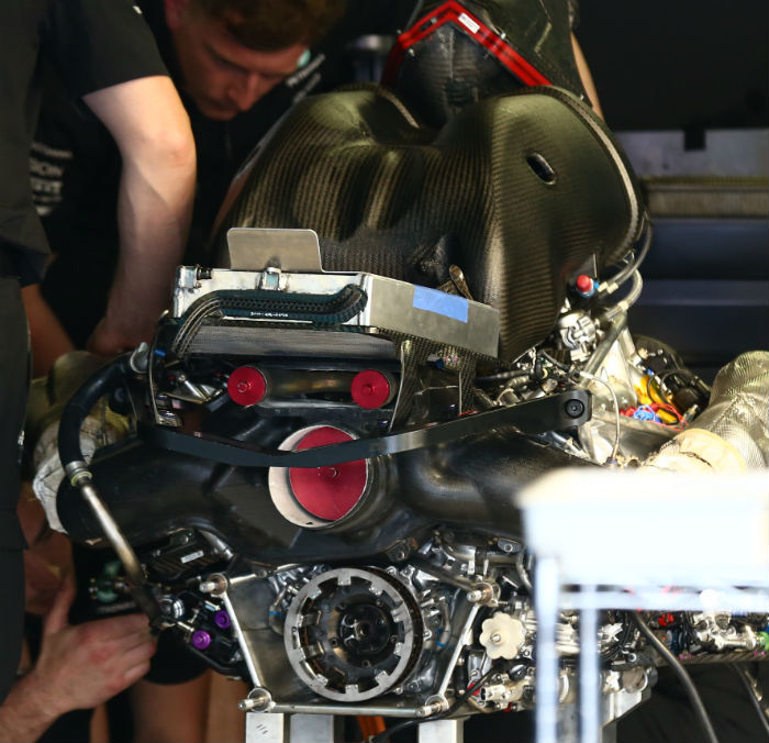
From the rear of the V6 engine it is possible to see the main exhaust exit (complete with red bung) and the twin wastegate exits above it (also with red bung). The shape of the plenum is clear to see as is the clutch basket.
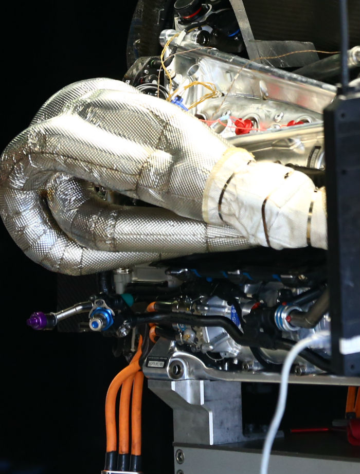
In this shot of the left hand side of the V6 engine it is possible to see part of the cylinder head, the exhaust headers and also just visible is the MGU-K. The orange cables hanging down from the base of the unit connect to the Energy store (battery)
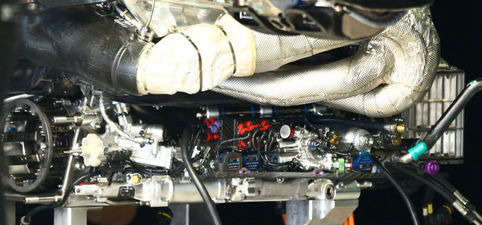
Looking at the right hand side of the V6 its possible to see a number of MOOG E024 servo valves, various hydraulic and electronic components, the clutch basket and on the far right of the image what appears to be part of a charge air cooler.
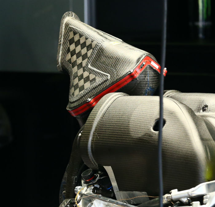
This image confirms that the combustion air is fed by the triangular central section of the main roll hoop duct. The side segments are used to feed coolers including (we think) a charge air cooler mounted near the front of the V6 block. Note the V shaped air filter housing.
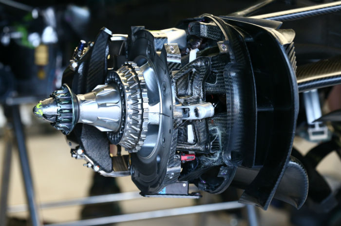
A look at the front brake setup with disc and some ducting removed.
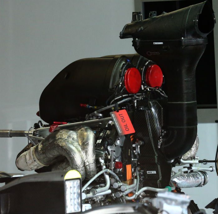
Here we get a nice clear look at the Mercedes power unit. In Malaysia one of the units suffered a bottom end bearing failure, though Mercedes HPP remain unclear as to the cause.
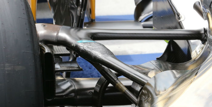
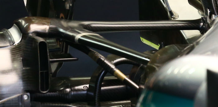
In Austria Mercedes beefed up its rear wishbones following a failure caused by that tracks aggressive kerbing. Compare the strengthened version (above) with the original spec (below). The wishbones reverted to the original concept for later races though the beefed up versions often make an appearance on the cars in travel specification.
Mercedes introduced an interesting front brake disc design at Monza (one assumes in collaboration with supplier Brembo which is based near Milan) it has a concave shape, possibly allowing for improved cooling.
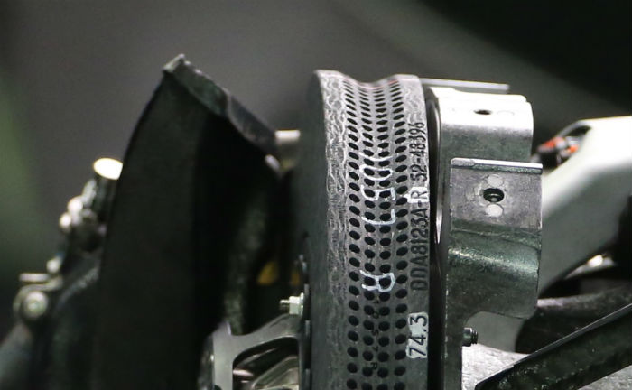
The concave shape could offer a larger surface area, making cooling of the disc easier. The rear discs remain conventional.

A new rear wing was introduced on the W07 with end plates inspired by those of the Toro Rosso with the open fronted vents. Actually the leading edges are all linked together but the effect is reportedly the same.
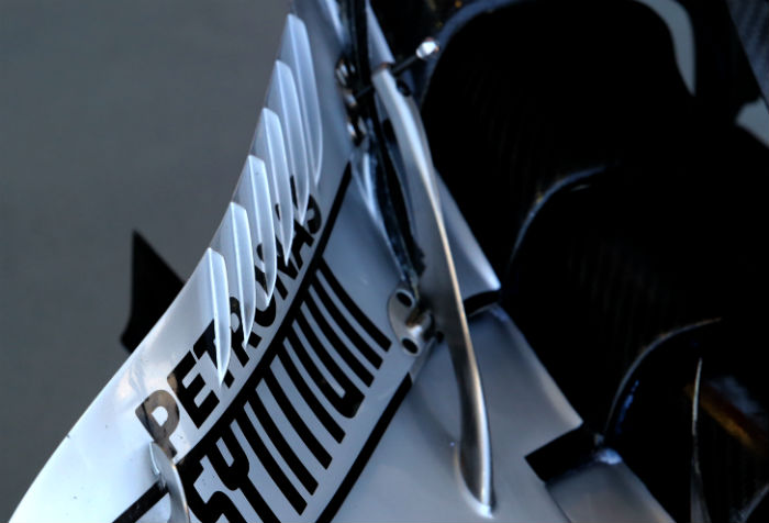
The front wing of the features a number of what appear to be vortex generators along the trailing edge of the upper element (above)
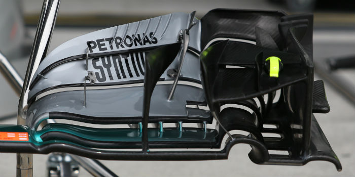
Compare with the alternative design Mercedes also had at Sepang (below) with the more commonly used version with the vortex generators (above).
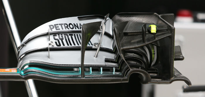
This level of detail on the wing shows the lengths to which the Mercedes team will go in pursuit of marginal gains.
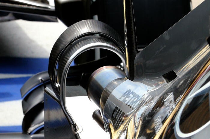
There have been various iterations of the rear winglet on the W07 during the season including a rounded version (above) and a squared off version (below)
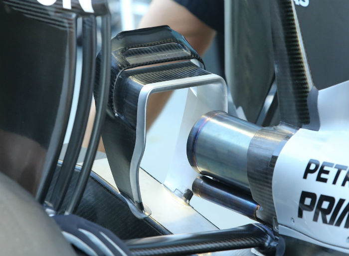
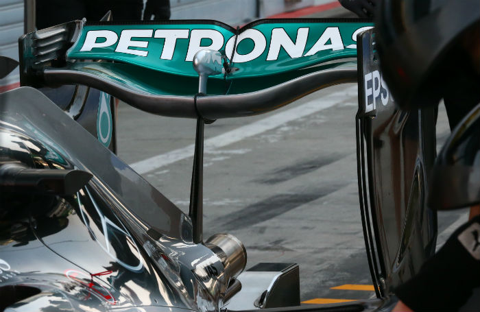
No winglet at all with the low drag rear wing used at Monza (below)
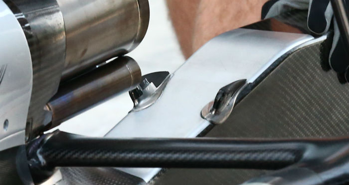
Note the two little mounting points for the winglets on the rear impact structure, they remained fitted to the car at Monza even though nothing was ever mounted to them.
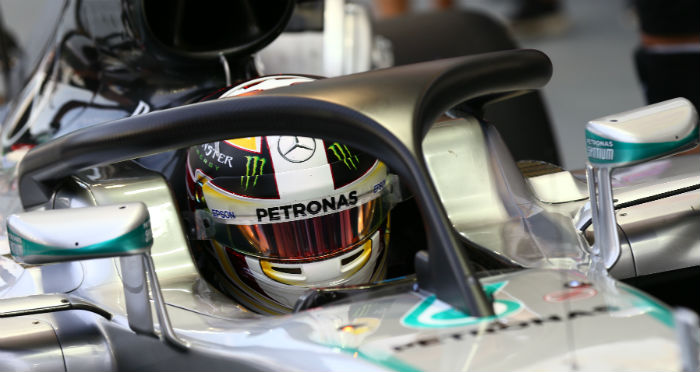
The W07 was fitted with a mock up of the Halo frontal protection system for some evaluation runs during the season.
