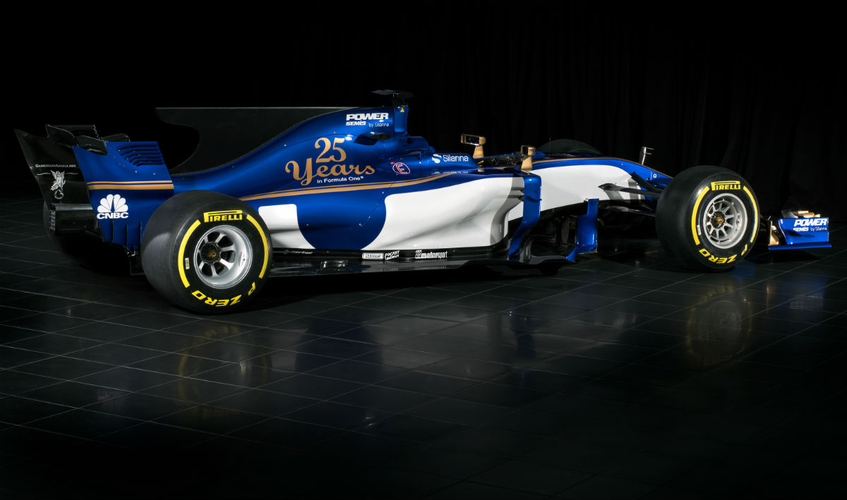
The Sauber C36 was the first proper 2017 F1 car to be revealed (Williams had earlier shown renders of its concept, and Manor’s wind tunnel model had leaked when the team collapsed). Sauber’s management set its technical staff the challenge of returning to the midfield in 2017 though many in the paddock expect the C36 to struggle to get out of Q1 at most races.
Jörg Zander has taken over as technical director at the team having departed Audi Sport. His arrival came too late however to have much if any influence on the design of the C36. The German summarised the most conspicuous changes that define the Sauber C36-Ferrari due to the new regulations for 2017 in the cars launch press material: “The cars are becoming wider again, from 1.80 to 2 metres, the tyres are 25 % wider, the front and rear wings are becoming wider as well, plus the diffuser is being enlarged. In total, this means more downforce, more grip and, as a result, faster lap times.”
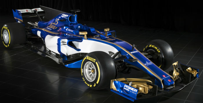
Consequently, work on the concept of the new car was focused on reducing the drag coefficient (due to the wider tyres) to a minimum as well as achieving a significant weight reduction, for instance by means of the new roll structure. In certain areas of lightweight design the team went to the limits. The aero concept includes the optimisation of the front and rear wings and the underfloor. The radiator, the sidepods and the bodywork were designed to be as slim as possible. Clear progress was also achieved in terms of additional downforce. The key here is to keep downforce, which is generated via driving, and remain stable in various track sections. “We put greater emphasis on aerodynamic stability as opposed to maximising downforce.”
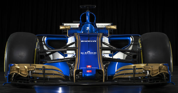
Zander continues and points out that the new rules could allow a bit more freedom in terms of car development. “With the wider tyres this year one might be able to mask deficits and get development concepts to work better.”
In 2017, the Ferrari powertrain in the Abu Dhabi 2016 configuration will be used initially together with the C36. One of the changes this season is that only four of the six units of a powertrain can be changed without penalty. In the next few years the number will be further reduced, which is why the manufacturers are going to put greater emphasis on the durability than on the top speed of their units. Jörg Zander regards the 2016-spec engine as “a tried and tested system with higher durability to begin with.” In addition, with respect to the design resources in planning the development of the C36, Jörg Zander says that “being able to get started early and defining the engine environment was an advantage because the team was familiar with the engine and the transmission as well as the cooling requirements the engine entailed.”
However the new regulations will place substantially higher demands on the power unit with not only an increased on throttle time but also much higher structural loads. It will be very interesting to see how the Ferrari unit copes with loads it simply was not designed to handle.
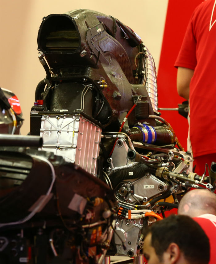
A look at the front end of the 2016 Ferrari power unit reveals a charge air cooler at the front of the engine block. The oil tank is on the right hand side of the front of the block.
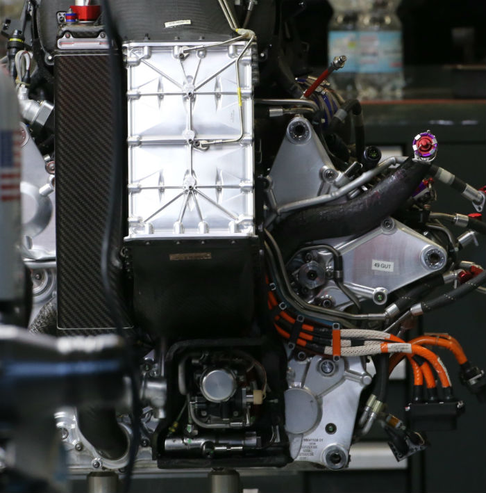
A look at the other side of the power unit with most of its heat shields removed, note the exhaust layout, oil tank and the air filter.
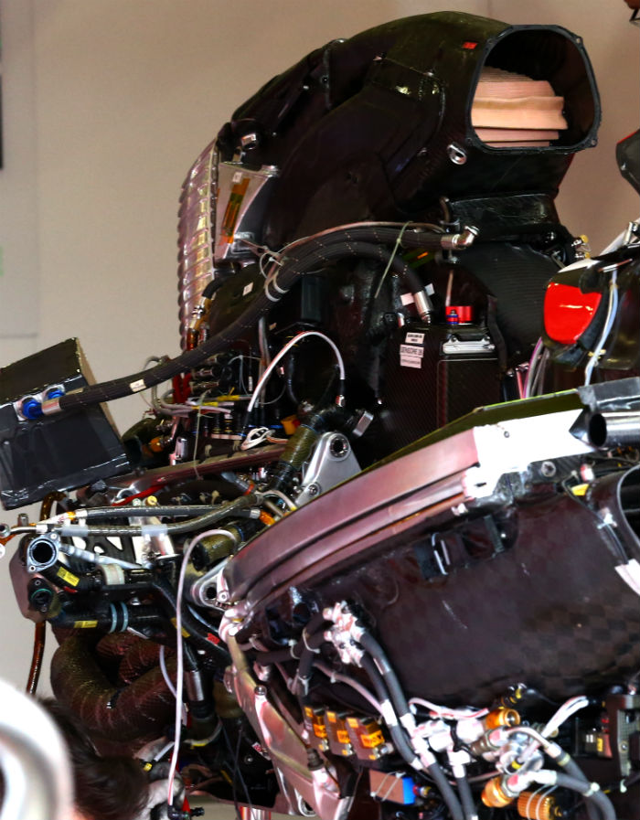
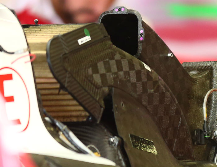
With some of the ducting removed it is possible to see the triangular shape of the air filter on the Ferrari V6.
One of the most striking details of the Sauber C36 is its lack of a roll hoop, instead of having the conventional hoop as a roll over structure with the main combustion air intake in the centre of that hoop the Sauber features a ‘blade’ with the air intakes for cooling and combustion either side of it. The central structure is the component which passes the crash tests and is meant to protect the driver in the event of a roll over accident.
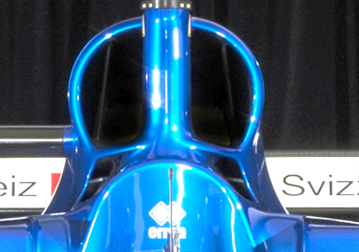
On the Sauber design the twin ducts either side of the roll structure are themselves split into segments (rather like the 2016 Mercedes and the 2017 Williams). The central and largest segments, those closest to the roll blade, feed the combustion air to the Ferrari V6 engine, the yellow air filter is just visible in the image above. The outer segments are separated from the combustion duct by a thin composite vane, these outer segments are likely for ERS cooling.
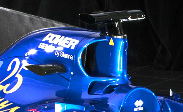
Below the main duct and to the side of the head rest further cooling ducts can be seen, note also the forward sweep of the roll hoop.
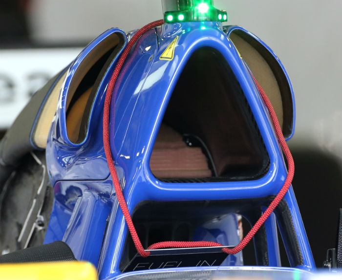
While the new roll hoop concept may offer additional or more efficient cooling the frontal area of the openings seem very similar to that of the C35 which also had additional ‘ears’ used for ERS cooling (above). These have been integrated into the main duct(s) on the C36.
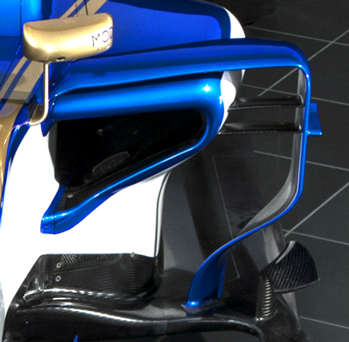
The main sidepod ducts on the C36 (above) are notably smaller than those seen on the C35 (below), this is perhaps surprising as the two cars share the same basic Ferrari power unit, yet in 2017 the unit will have a much higher on throttle time so could perhaps be expected to require more cooling that it did in 2016. Note the bi-plane elements linking the outer edge of the sidepod to the flow conditioner/pod wing around its leading edge, and the small flick up on the outer edge.
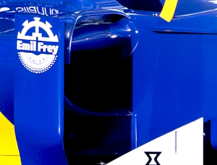
The aerodynamic complexity around the leading edge of the sidepod is noteworthy (below), clearly Sauber has been able to work more in its own wind tunnel than in recent years, largely thanks to the withdrawal of Audi Sport from LMP1, the German brand had utilised Sauber’s aerodynamic facilities heavily in recent years, to the detriment of the F1 programme.
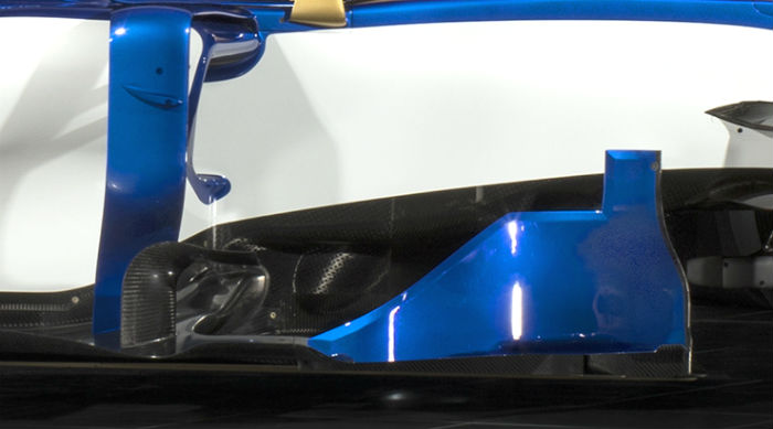
The rearward sweep of the sidepods is visible in this image as are the larger bargeboards allowed under the 2017 regulations.
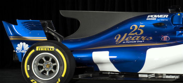
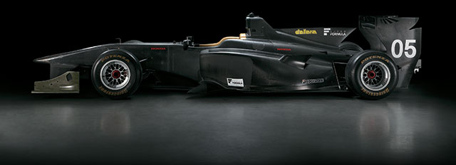
Looking at the rear of the car the, rear ward sweep of the rear wing endplates is clear to see as is the large fin on the engine, these are more prevalent on 2017 designs than in recent years as a result of the introduction of the new lower rear wings. Notably, Super Formula (below), the only other series in the world with apex speeds in the range expected to be seen in F1 2017, also uses large fins on its cars in order to control air flow to the rear wing in yaw.
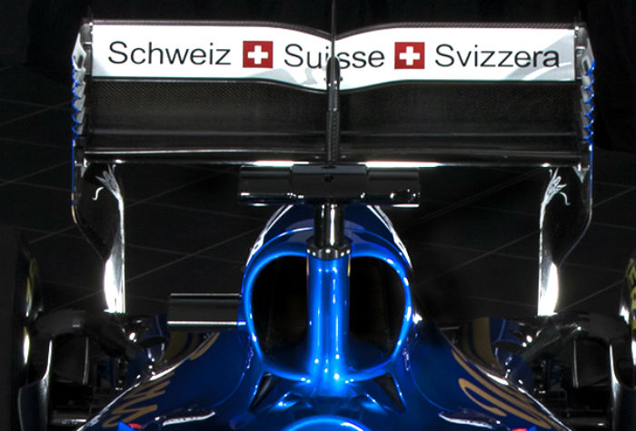
The rear wing endplates are of interest, note how they sweep inward at the base, this is a feature of many cars on the ’17 F1 grid and is thought to do with the air flow off the rotating rear tyre.
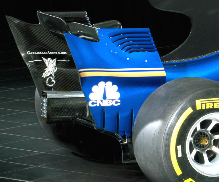
The leading edge of the upper part of the rear wing endplate features an array of six vents, which are almost open ended but are still linked by a very small piece of material, an approach pioneered by Toro Rosso. At the trailing edge it appears that there is a small vertical wicker on the endplate, just where the twin yellow lines end. Note how the endplate joins to the upper section of the diffuser (below).
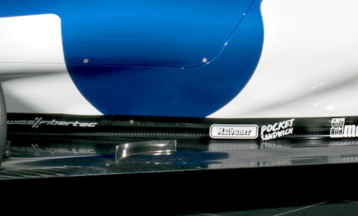
Note this small turning vane on the floor ahead of the rear tyre, a lot more development is expected in this area of the car (below)
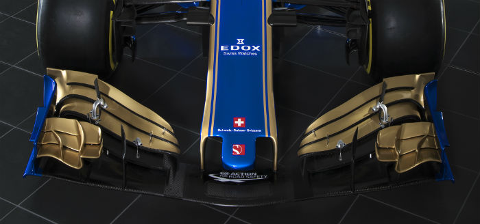
The front wing by regulation features a rearward sweep, while the wing seems complex in this launch/testing specification, extensive development is expected in this area.
